








Why Does an RV Reducer Need Profile Modification? How to Further Reduce Backlash and Transmission Error?
In robotic joints, precision rotary tables, and heavy-duty precision transmission systems, the accuracy of an RV reducer is not determined by machining accuracy alone. Cycloidal gear profile modification, pin engagement, crankshaft eccentricity, bearing clearance, assembly accuracy, load-induced deformation, and thermal deformation all contribute to the backlash and transmission error measured at the output.
For this reason, profile modification in an RV reducer is not simply a matter of “making the teeth slightly smaller,” nor is it intended to create a larger clearance. More precisely, profile modification introduces a controlled amount of clearance into the theoretical conjugate tooth profile so that the RV reducer can maintain stable meshing under real operating conditions where manufacturing tolerances, assembly errors, load deformation, and thermal deformation coexist.
For a high-precision RV reducer, the objective is therefore not simply to pursue “zero backlash,” but to achieve a practical balance between minimum usable clearance, multi-tooth load sharing, low backlash, low transmission error, and long-term reliability.
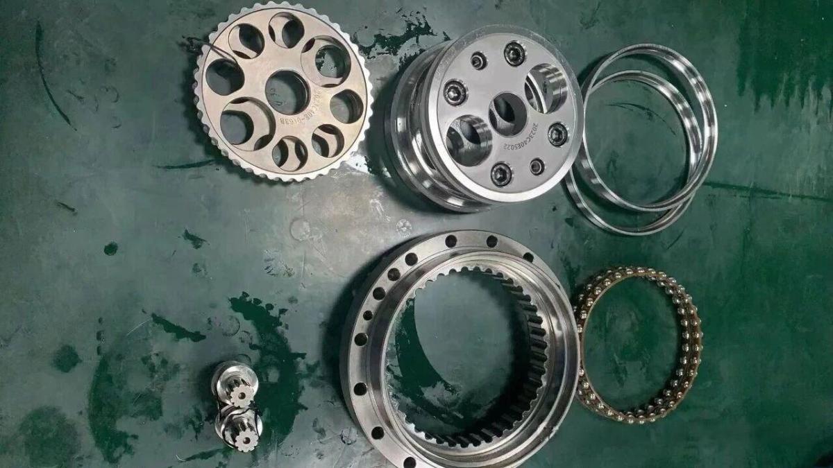
Why Can't a Theoretical Zero-Clearance Cycloidal Profile Be Used Directly?
The second-stage transmission of an RV reducer uses cycloidal discs and pins. Under ideal geometric conditions, a cycloidal profile generated according to the theoretical conjugate profile can achieve extremely close engagement.
However, a real RV reducer is not an ideal geometric system.
The cycloidal disc profile, pin-hole position, pin radius, crank eccentricity, bearing clearance, and assembly relationships between individual components all contain manufacturing tolerances. If the design attempts to achieve near-zero clearance based purely on the theoretical tooth profile, the resulting high theoretical precision may instead create more serious problems during actual assembly and operation.
Manufacturing and Assembly Errors Change the Actual Meshing Condition
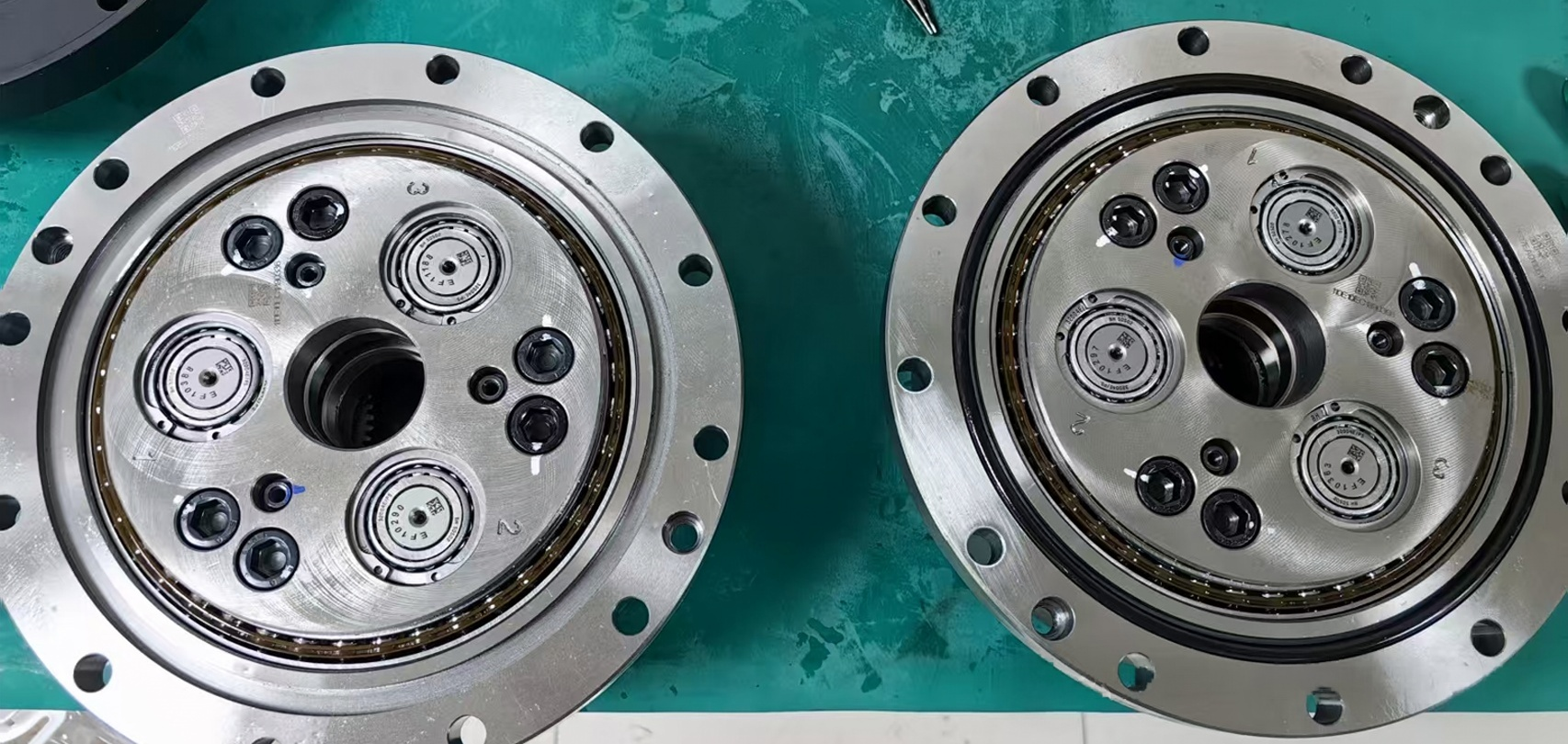
An RV reducer contains a large number of precision components. The cycloidal discs, pin housing, crankshaft, planetary mechanism, main bearings, and crank bearings form a complex dimensional and positional chain.
For example, the cycloidal disc has profile deviations, the pin holes have positional tolerances, the pin radius has dimensional deviations, the crank has eccentricity errors, the bearings have clearance and manufacturing tolerances, the two cycloidal discs may have phase errors, and the housing and output structure may contain geometric deviations.
After these errors are accumulated, the actual center position of the assembled system may deviate from the theoretical position even when every individual component meets its specified tolerance.
Without appropriate profile modification and clearance design, local interference or excessive contact pressure can therefore occur.
Load-Induced Elastic Deformation Changes the Theoretical Tooth Profile
When an RV reducer operates under rated torque, the cycloidal discs, pins, crankshaft, bearings, and housing all undergo a certain degree of elastic deformation.
This includes deformation at the pin-to-cycloidal-disc contact, bending of the cycloidal disc, torsional deformation of the crankshaft, elastic deformation of the bearings, and deformation of the output flange and housing.
As a result, the ideal meshing condition observed during cold, no-load operation is not necessarily the same as the meshing condition under rated load.
If profile modification only considers geometric errors while ignoring load-induced deformation, the actual contact region can shift during operation, causing transmission error to vary with torque.
This is why the design of high-precision RV reducers increasingly needs to move from simple geometric profile modification toward load-dependent deformation compensation.
Thermal Deformation Also Changes RV Reducer Clearance
After an RV reducer operates continuously, the temperature of the lubricant increases, and the cycloidal discs, pins, pin housing, and other components undergo thermal expansion.
A clearance that is appropriate at room temperature may therefore become smaller once the reducer reaches thermal equilibrium.
If the initial clearance is too small, thermal expansion may cause local interference, increased friction, and excessive temperature rise.
For this reason, RV reducer profile modification needs to provide an appropriate operating clearance across the expected temperature range rather than being designed only for the cold condition.
Lubrication Also Requires Appropriate Meshing Clearance
An RV reducer uses multiple teeth in simultaneous engagement. If the contact areas are excessively tight, lubricant flow into the actual contact region may be affected, while friction and heat generation can increase.
The purpose of profile modification is therefore not simply to increase clearance. The objective is to maintain effective tooth engagement while leaving sufficient space for lubrication, thermal expansion, manufacturing tolerances, and assembly errors.
This is another reason why high-precision RV reducers do not simply pursue theoretical zero clearance.
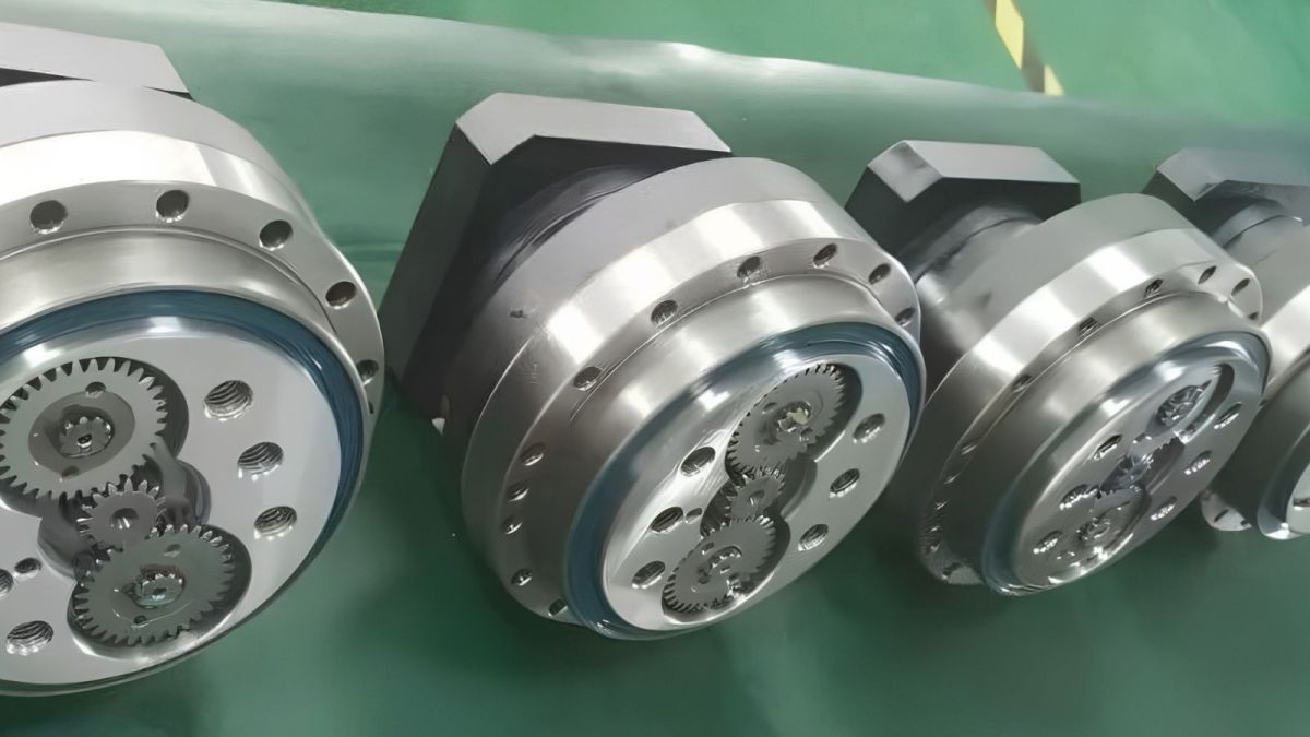
What Are the Common Profile Modification Methods for RV Reducers?
The basic principle of cycloidal disc profile modification is to make a small adjustment to the actual working profile based on the theoretical tooth geometry.
Depending on the direction and method of modification, common approaches include equidistant modification, displacement modification, angular modification, and combined modification.
Equidistant Profile Modification
Equidistant modification adjusts the theoretical cycloidal profile by a small amount along the normal direction of the tooth profile. It can be understood as a controlled offset of the theoretical profile, which changes the actual meshing clearance.
This method is relatively straightforward in terms of calculation and manufacturing, making it a practical approach for cycloidal disc design.
However, a purely equidistant modification also has limitations. If exactly the same modification amount is applied to the entire profile, it may be difficult to simultaneously satisfy the requirements for working-region engagement, tooth-tip clearance, tooth-root clearance, and compensation for load-induced deformation.
Displacement Modification
Displacement modification adjusts the meshing condition by changing geometric parameters related to the center distance.
This method can have a significant influence on the actual meshing condition of an RV reducer. It is therefore often combined with other modification methods rather than being used as the only profile modification strategy.
A properly selected displacement can help improve the working-region contact condition and reduce the possibility of local interference.
Angular Profile Modification
Angular modification adjusts the overall angular position of the cycloidal disc and regenerates the corresponding profile.
In theory, this approach can make the working region closer to an ideal conjugate relationship while creating the necessary clearance in non-working regions.
However, it places higher requirements on profile generation, machining, and inspection, so manufacturing cost and process consistency need to be considered.
Combined Equidistant and Displacement Modification
In practical RV reducer design, combined modification provides greater flexibility than relying on a single modification method.
By combining equidistant and displacement modification, engineers can adjust the working-region engagement, non-working-region clearance, number of simultaneously engaged teeth, contact distribution, backlash, and contact stress.
For a high-precision RV reducer, the most important question is therefore not simply which modification method is used, but what kind of operating clearance and load distribution the final profile produces.
Does a Smaller Modification Amount Always Mean Higher RV Reducer Accuracy?
This is a common misconception in RV reducer design.
From a geometric perspective, increasing the modification amount generally increases the resulting clearance, which can also increase geometric backlash.
However, this does not mean that continuously reducing the modification amount will produce a more accurate RV reducer.
If the profile modification is insufficient, the reducer may experience local interference, concentrated contact stress, increased friction, higher temperature, poorer lubrication conditions, increased noise, reduced thermal stability, and accelerated long-term wear.
The real objective of RV reducer profile modification is therefore the minimum usable clearance rather than theoretical zero clearance.
At the same time, sufficient effective tooth engagement and an appropriate load distribution must be maintained.
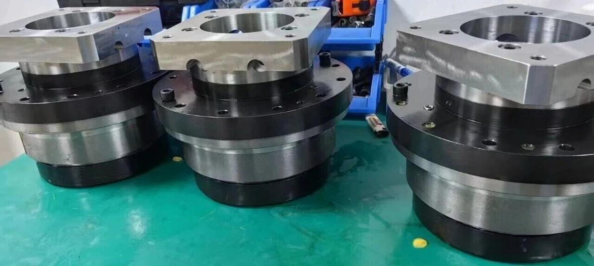
Why Can't RV Reducer Backlash Be Controlled by Profile Modification Alone?
Backlash is an important indicator of RV reducer precision, but it is not determined by the cycloidal tooth profile alone.
Actual backlash is the combined result of multiple error sources, including cycloidal disc profile and modification errors, pin distribution errors, crank eccentricity, bearing clearance, phase error between the two cycloidal discs, first-stage planetary transmission error, output flange and housing deformation, assembly errors, and thermal deformation.
Therefore, if an RV reducer still has excessive backlash after the cycloidal profile has been optimized, simply reducing the modification amount further is often not the most effective solution.
A more effective approach is to establish a complete backlash error budget and determine how much each source contributes to the final output error.
What Is the Difference Between RV Reducer Backlash and Transmission Error?
Backlash and transmission error are often discussed together, but they describe different aspects of reducer performance.
Backlash primarily reflects the lost motion or clearance that becomes apparent when the direction of rotation is reversed.
Transmission error, on the other hand, describes the deviation between the actual output motion and the theoretically expected output motion.
For robotic joints, both can influence the final positioning performance.
In high-precision robots, precision rotary tables, and high-response servo systems, a reducer may have relatively small static backlash while still exhibiting noticeable periodic transmission error. In such cases, the output may still experience positioning fluctuations.
Therefore, a high-precision RV reducer should not be evaluated solely by pursuing a very small backlash value.
The actual target is better understood as the combined control of backlash, periodic transmission error, load-dependent error, and thermal-state-dependent error.
Why Can Transmission Error Change After an RV Reducer Is Loaded?
This is an important issue in the design of high-precision RV reducers.
Under no-load conditions, the actual contact position between the cycloidal disc and pins is primarily determined by geometric errors.
Once torque is applied, however, the contact region changes.
As load increases, the pin contact undergoes elastic deformation, the cycloidal disc bends slightly, the crankshaft experiences torsional deformation, the bearings undergo elastic displacement, and the output structure deforms. As a result, the actual meshing region is redistributed.
Therefore, a cycloidal profile optimized under no-load conditions may not maintain the same transmission error under rated torque.
This is one of the reasons why high-precision RV reducer development is moving from geometric profile modification toward load-dependent profile compensation.
How Can Elastic Compensation Further Reduce RV Reducer Transmission Error?
When the objective is to reduce transmission error under loaded conditions, engineers can establish a structural deformation model of the RV reducer.
The basic process is to start with the theoretical profile, apply geometric modification, introduce the actual operating load, calculate the resulting contact deformation, determine the resulting meshing displacement, and then modify the profile in the opposite direction to compensate for the predicted deformation.
This approach is commonly understood as load-dependent profile modification or elastic deformation compensation.
The purpose is not simply to increase clearance. Instead, the modification amount is designed to correspond to the direction and magnitude of deformation generated under the actual operating load.
For applications such as robotic joints and precision rotary tables where transmission error is particularly important, this approach can provide a more systematic path toward improving loaded accuracy.
What Other Factors Affect RV Reducer Transmission Error?
If the cycloidal profile has already been optimized but transmission error remains excessive, the other error sources within the RV reducer need to be examined.
Crankshaft and Crank Bearing
The crankshaft is a critical component for transmitting motion and load in an RV reducer.
Crank eccentricity, bearing clearance, and bearing stiffness all affect the final output motion.
If these factors are not included in the error budget, optimizing the cycloidal profile alone may not provide stable low transmission error.
Phase Relationship Between the Two Cycloidal Discs
A dual-cycloidal-disc RV reducer requires the two discs to maintain the specified phase relationship.
If assembly introduces excessive phase deviation, load distribution and output motion error can be affected.
For this reason, high-precision RV reducers require reliable control of the phase relationship during assembly.
Pin Housing and Pin-Hole Position Accuracy
The positional accuracy of the pin holes directly determines the actual distribution of the pins.
If the pin distribution contains significant positional errors, even a highly accurate theoretical cycloidal profile cannot produce the desired meshing condition.
The machining accuracy and assembly datum of the pin housing are therefore important factors in controlling RV transmission error.
First-Stage Planetary Transmission
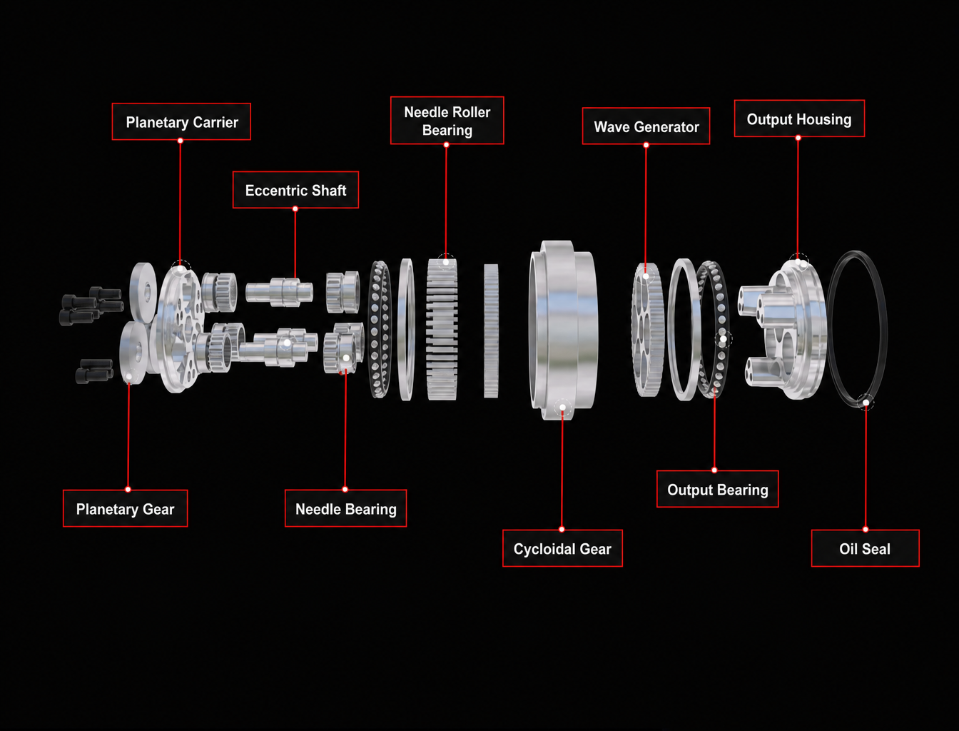
An RV reducer does not consist only of the second-stage cycloidal transmission.
The first-stage sun gear, planetary gears, and carrier also contribute to motion error.
Although the effect of some errors is reduced or transformed through the transmission ratio, the first-stage planetary mechanism still needs to be included in the overall error analysis of a high-precision RV reducer.
Output Flange and Main Bearing Stiffness
Insufficient output stiffness can cause the output flange to undergo small displacements when the external load changes.
For robotic joints and precision rotary tables, these displacements can eventually appear as output positioning errors.
Therefore, a low-backlash RV reducer requires not only an optimized cycloidal profile but also sufficient stiffness throughout the output structure.
How Can an RV Reducer Backlash Error Budget Be Established?
If the objective is to manufacture a consistently low-backlash RV reducer, all precision requirements should not be placed on the cycloidal disc.
A more practical approach is to separate the major backlash sources, including cycloidal profile modification error, pin distribution error, crank eccentricity, bearing clearance, phase error, first-stage transmission error, assembly error, and output structural deformation.
An allowable range can then be established for each source according to its sensitivity and contribution to the final output error.
This approach has two major advantages. First, it helps identify which error sources actually dominate the final backlash. Second, it prevents engineers from repeatedly increasing the machining accuracy of one component simply to compensate for errors elsewhere in the system.
For example, if the dominant source of backlash is crank eccentricity, further reducing the cycloidal profile error may produce little improvement.
This is why error budgeting and sensitivity analysis are essential in the development of high-precision RV reducers.
How Should RV Reducer Profile Modification Work Together With Manufacturing Tolerances?
Profile modification and manufacturing tolerances solve different problems and should not be treated as substitutes for one another.
Profile modification is primarily used to control the average meshing behavior of the system under operating conditions, while manufacturing tolerances control the variation between individual components.
A simple way to understand the relationship is:
Profile modification compensates for system behavior, while tolerances control manufacturing variation.
If the machining accuracy of the components is insufficient, increasing cycloidal profile modification to compensate for every error will eventually result in excessive clearance and poorer backlash performance.
On the other hand, extremely tight component tolerances cannot compensate for load-induced or thermal deformation if those effects have not been considered in the design.
A more systematic approach combines profile modification, tolerance design, assembly control, structural stiffness, and thermal deformation analysis.
How Should an RV Reducer Be Tested After Profile Modification?
After profile modification has been completed, the design should not be judged solely by a single static backlash value.
A more complete validation process should evaluate the reducer under different operating conditions.
Step 1 — No-Load Testing
The first stage is to measure output motion error and backlash at a controlled low speed under no-load conditions.
The evaluation should focus on the maximum backlash, periodic error, error waveform, angular position dependence, and differences between forward and reverse motion.
If a clear periodic pattern appears in the error curve, further analysis should determine whether it is associated with eccentricity, pin distribution, phase relationship, or other geometric errors.
Step 2 — Testing Under Different Loads
The reducer should then be tested under light and rated loads.
If transmission error is relatively small at no load but increases significantly as the load increases, structural elastic deformation and changes in the contact condition may be the dominant factors.
The load-dependent deformation model and profile compensation should then be reviewed.
Step 3 — Thermal Stability Testing
For RV reducers operating continuously, thermal stability also needs to be evaluated.
Changes in lubricant temperature, backlash, transmission error, noise, and temperature rise should be monitored as the reducer approaches thermal equilibrium.
If a significant difference exists between cold and thermally stabilized conditions, the clearance changes caused by thermal expansion should be reconsidered.
Step 4 — Running-In Testing
The purpose of running-in should be to gradually stabilize the contact area rather than using excessive load to mechanically force the tooth surfaces into an acceptable condition.
A controlled running-in process should begin under moderate load and speed before gradually moving toward normal operating conditions.
If a reducer requires prolonged high-load running-in to eliminate obvious interference, the underlying problem should normally be addressed through profile modification, machining accuracy, or assembly control rather than being concealed through aggressive running-in.
What Does a High-Precision RV Reducer Really Need to Control?
The accuracy of an RV reducer is not determined by one individual component.
Its final performance is the result of an integrated system involving tooth profile, profile modification, meshing, bearings, crankshaft, pin housing, assembly, load deformation, thermal deformation, and output structure.
Therefore, when trying to further reduce backlash and transmission error, the key question is not simply:
“How much should the cycloidal profile be modified?”
A more useful engineering question is:
“Under the actual operating load and temperature conditions, how much usable clearance does the complete transmission system require, and how should the individual error sources be allocated?”
This represents an important shift from conventional geometric design toward system-level precision engineering for high-performance RV reducers.
HONPINE RV Precision Gear Reducer Design Focus
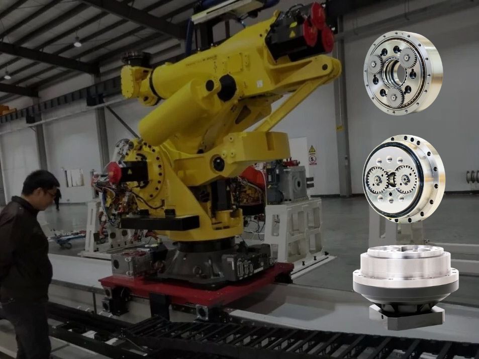
For robotic joints, heavy-duty robotic arms, industrial rotary tables, precision rotary mechanisms, and CNC equipment, an RV reducer must often handle substantial output torque while maintaining stable backlash, stiffness, and transmission accuracy over long-term operation.
For this reason, the performance of an RV reducer should not be evaluated through a single backlash specification.
A more complete engineering evaluation should consider backlash, transmission error, torsional stiffness, load capacity, efficiency, thermal stability, bearing life, and manufacturing consistency as an integrated set of performance requirements.
For HONPINE, the development of RV Precision Gear Reducers also needs to extend beyond the dimensional accuracy of individual components toward the performance of the complete transmission system. Cycloidal profile modification is only one part of this process. Long-term performance depends on the interaction between tooth profile design, precision machining, component tolerances, bearing matching, assembly processes, load characteristics, and validation testing.
Conclusion — The Goal of RV Reducer Profile Modification Is Not Zero Clearance
The real purpose of RV reducer profile modification is not to make the cycloidal disc increasingly close to the theoretical tooth profile, nor is it simply to pursue zero clearance.
A more appropriate objective is to achieve minimum usable clearance, stable multi-tooth engagement, appropriate load distribution, and controlled transmission error under real operating conditions where manufacturing errors, assembly errors, load deformation, thermal deformation, and lubrication conditions all exist simultaneously.
The optimization process for a high-precision RV reducer should therefore form a complete engineering loop:
Theoretical profile → Cycloidal profile modification → Error budgeting → Load deformation analysis → Tolerance design → Precision machining → Assembly control → No-load and load testing → Thermal stability validation → Profile modification iteration
Only by coordinating these stages can an RV reducer achieve genuinely low backlash and controlled transmission error, rather than relying on a single tooth-profile parameter to pursue precision.
Read More
Learn more about the story of HONPINE and industry trends related to precision transmission.
 What is robot joint actuator?How to Choose the Best Robot Rotary Joint Actuator?In core robot joint transmission solutions, planetary and harmonic rotary actuators each have their own strengths. Choosing the right type based on application requirements is essential to achieve the optimal balance between performance and cost.
 DD Motors VS Harmonic Rotary ActuatorsThis article provides an in-depth comparison between Direct Drive (DD) motors and harmonic rotary actuators, covering their transmission principles, advantages and disadvantages, and typical application fields.
 OMG Ultra Compact Harmonic Drive Joint Module with Built-in Torque SensorHONPINE TCHL series harmonic drive joint module is a game-changing product that achieves disruptive improvements in multiple aspects such as lightweight design, integration level, and connection convenience. This article will analyze its revolutionary enhancements with you.
 The Role of Harmonic Drive Gears in Achieving 5–10 μm Accuracy in Dental Milling MachinesA dental milling machine is a CNC machining system used to directly process digital dental models into restorations such as crowns, bridges, veneers, inlays, and implant abutments. Dental milling machines require far higher operational accuracy and motion stability than ordinary equipment. This article explains how harmonic drive gear help dental milling machines achieve stable, continuous, and controllable operation.
 Why Are Harmonic Rotary Actuators Perfect for Medical Equipment?Harmonic rotary actuators (typically integrated systems consisting of a harmonic drive reducer, frameless torque motor, encoder, and optional brake) are regarded as key components in medical equipment. The core reason is that they simultaneously meet the most stringent medical requirements for precision, compact size, safety, and controllability. The following explanation is structured from three perspectives: technical characteristics, application scenarios, and medical value.
 High-Precision RV Reducers Perfectly Matched for Walking RobotsThe walking axis of a robot is a core component for power transmission and support. RV reducers provide extremely high rigidity, precision, and torque while maintaining a compact size and exceptional reliability, making them an ideal match for the demanding requirements of walking robot joints in terms of load capacity, impact resistance, and precision.
 Why Does an RV Reducer Need Profile Modification? How to Further Reduce Backlash and Transmission Error?An RV Reducer is designed to deliver high torque, high stiffness, and precise motion for demanding applications such as robotic joints, industrial rotary tables, and precision machinery. However, achieving low backlash and stable transmission accuracy requires more than high-precision machining. Cycloidal profile modification must also account for manufacturing tolerances, assembly errors, load-induced deformation, thermal expansion, and lubrication conditions. In this article, we examine why RV reducers require profile modification, how different modification methods affect meshing, and how engineers can further control backlash and transmission error through profile design, error budgeting, structural analysis, precision manufacturing, and validation testing.
 Hollow Robot Joint Module: Why Cable Routing Matters in Robotic Joints?A hollow robot joint module provides an internal passage for power cables, signal lines, pneumatic tubes, and other end-effector connections. Compared with external cable routing, a hollow joint module can help reduce cable exposure, improve system integration, and create a cleaner motion path for robotic arms. This article explains why internal cable routing matters in robotic joints and what to consider when selecting a hollow joint module for robotic applications.
 Robot Joint Actuator Selection: From Inertia Matching to System-Level OptimizationSelecting a robot joint actuator is not simply a matter of matching motor torque or achieving a suitable inertia ratio. In a real robotic system, reduction ratio, load spectrum, thermal performance, mechanical stiffness, transmission nonlinearity, encoder architecture, control bandwidth, and service life all interact to determine the final result. A joint may meet its peak torque requirement and still experience vibration, overheating, positioning errors, or premature wear in real operation. This article examines the engineering logic behind robot joint actuator selection and explains why moving from single-parameter matching to system-level optimization can lead to more reliable and predictable robotic joint performance.
 HONPINE HAG Robot Joint Module Undergoing Pre-Shipment InspectionThe HONPINE HAG Robot Joint Module is currently undergoing pre-shipment inspection before delivery.
 How to Choose a Small Harmonic Actuator?HONPINE Series 11 small harmonic actuators provide a compact, high-performance rotary motion solution for precision automation applications. Available with hollow or solid shafts, 48V or 220V options, optional brakes, absolute encoders, and different reduction ratios, the Series 11 is designed for applications requiring compact dimensions, controlled torque, and precise positioning.
 How to Choose a Wheel Motor for a Heavy-Duty AGV? Key Challenges from Dynamic Loads to 120-Ton AGV Drive Wheel SystemsSelecting a Heavy-Duty AGV Wheel Motor is more than matching motor power or rated torque to the vehicle's payload. As AGVs move from conventional material handling to multi-ton and even 120-ton-class applications, the drive wheel system must handle dynamic loads, acceleration, braking, turning forces, traction, and long-term mechanical stress. The actual challenge lies in matching wheel load capacity, wheel-end torque, gearbox performance, steering architecture, suspension, and chassis design under real operating conditions. This article examines the key challenges of Heavy-Duty AGV Wheel Motor selection and explains how Steering Drive Wheels and Differential Drive Wheels can be evaluated for different heavy-duty AGV applications.
Double Click
We provide harmonic drive reducer,planetary reducer,robot joint motor,robot rotary actuators,RV gear reducer,robot end effector,dexterous robot hand
 What is robot joint actuator?How to Choose the Best Robot Rotary Joint Actuator?In core robot joint transmission solutions, planetary and harmonic rotary actuators each have their own strengths. Choosing the right type based on application requirements is essential to achieve the optimal balance between performance and cost.
 DD Motors VS Harmonic Rotary ActuatorsThis article provides an in-depth comparison between Direct Drive (DD) motors and harmonic rotary actuators, covering their transmission principles, advantages and disadvantages, and typical application fields.
 OMG Ultra Compact Harmonic Drive Joint Module with Built-in Torque SensorHONPINE TCHL series harmonic drive joint module is a game-changing product that achieves disruptive improvements in multiple aspects such as lightweight design, integration level, and connection convenience. This article will analyze its revolutionary enhancements with you.
 Why Does an RV Reducer Need Profile Modification? How to Further Reduce Backlash and Transmission Error?An RV Reducer is designed to deliver high torque, high stiffness, and precise motion for demanding applications such as robotic joints, industrial rotary tables, and precision machinery. However, achieving low backlash and stable transmission accuracy requires more than high-precision machining. Cycloidal profile modification must also account for manufacturing tolerances, assembly errors, load-induced deformation, thermal expansion, and lubrication conditions. In this article, we examine why RV reducers require profile modification, how different modification methods affect meshing, and how engineers can further control backlash and transmission error through profile design, error budgeting, structural analysis, precision manufacturing, and validation testing.
 Hollow Robot Joint Module: Why Cable Routing Matters in Robotic Joints?A hollow robot joint module provides an internal passage for power cables, signal lines, pneumatic tubes, and other end-effector connections. Compared with external cable routing, a hollow joint module can help reduce cable exposure, improve system integration, and create a cleaner motion path for robotic arms. This article explains why internal cable routing matters in robotic joints and what to consider when selecting a hollow joint module for robotic applications.
 Robot Joint Actuator Selection: From Inertia Matching to System-Level OptimizationSelecting a robot joint actuator is not simply a matter of matching motor torque or achieving a suitable inertia ratio. In a real robotic system, reduction ratio, load spectrum, thermal performance, mechanical stiffness, transmission nonlinearity, encoder architecture, control bandwidth, and service life all interact to determine the final result. A joint may meet its peak torque requirement and still experience vibration, overheating, positioning errors, or premature wear in real operation. This article examines the engineering logic behind robot joint actuator selection and explains why moving from single-parameter matching to system-level optimization can lead to more reliable and predictable robotic joint performance.
 How to Choose a Small Harmonic Actuator?HONPINE Series 11 small harmonic actuators provide a compact, high-performance rotary motion solution for precision automation applications. Available with hollow or solid shafts, 48V or 220V options, optional brakes, absolute encoders, and different reduction ratios, the Series 11 is designed for applications requiring compact dimensions, controlled torque, and precise positioning.
 How to Choose a Wheel Motor for a Heavy-Duty AGV? Key Challenges from Dynamic Loads to 120-Ton AGV Drive Wheel SystemsSelecting a Heavy-Duty AGV Wheel Motor is more than matching motor power or rated torque to the vehicle's payload. As AGVs move from conventional material handling to multi-ton and even 120-ton-class applications, the drive wheel system must handle dynamic loads, acceleration, braking, turning forces, traction, and long-term mechanical stress. The actual challenge lies in matching wheel load capacity, wheel-end torque, gearbox performance, steering architecture, suspension, and chassis design under real operating conditions. This article examines the key challenges of Heavy-Duty AGV Wheel Motor selection and explains how Steering Drive Wheels and Differential Drive Wheels can be evaluated for different heavy-duty AGV applications.
 DD Motor Servo System: How to Understand Mechanical Resonance and Solve Machine Vibration?This article explains the relationship between DD motor servo tuning, mechanical resonance, and servo bandwidth in direct drive motion systems. It examines why vibration and instability can occur even after repeated servo parameter adjustments, and explains how mechanical stiffness, moving mass, bearing conditions, load distribution, and structural geometry affect resonance frequency. The article also compares approaches for high- and low-frequency resonance, explains when digital notch filtering can be effective, and provides a practical tuning strategy for engineers working with DD motors, direct drive torque motors, and linear motors.
 Why Do Industrial Robots and Heavy-Duty Equipment Prefer Dual-Disc RV Reducers?Many engineers have the same question when they first look inside an RV reducer: if a single cycloidal disc can already achieve speed reduction, why do industrial robot RV reducers almost always use two discs? The additional disc increases the number of components, assembly complexity, and manufacturing cost, so its purpose deserves a closer look. The answer is not simply a higher reduction ratio. A dual-disc RV reducer is designed to improve the overall mechanical behavior of the transmission through better force balance, load sharing, backlash control, torsional stiffness, and long-term reliability. In this article, we use an RV reducer assembly model and motion simulation to examine these mechanisms and explain why the dual-disc architecture is widely used in industrial robots, machine tools, rotary tables, and other heavy-duty precision transmission systems.
 Small Size Harmonic Drive Reducer: Advantages, Applications and Selection GuideSmall size harmonic drive reducer for compact precision motion systems, offering high reduction ratio, near-zero backlash, low weight and accurate transmission.
 High Precision Harmonic Drive Robot Joint Actuator Solution for Robotic ElbowsThe robotic elbow joint plays a critical role in arm flexion, posture adjustment, and end-effector positioning. As humanoid robots, collaborative robots, and robotic arms become more capable, elbow actuators need to deliver high torque and precise motion within increasingly limited installation spaces. A high precision harmonic drive robot joint actuator integrates the harmonic reducer, motor, encoder, brake, and drive system into a compact unit, providing low backlash, high stiffness, high torque density, and accurate motion control. In this article, HONPINE introduces three joint actuator series suitable for robotic elbow applications, covering different requirements for size, torque, speed, precision, and integration.