







How Does the HONPINE HPJM Integrated Robot Joint Module Deliver High Torque in a Compact Space?
As robots become more compact and increasingly sophisticated, robot manufacturers face a common engineering challenge: how can they achieve higher output torque without increasing the installation space occupied by each joint?
The HONPINE HPJM integrated robot joint module addresses this challenge through a combination of compact mechanical integration, optimized cable routing, and space-efficient installation structures. Rather than focusing solely on reducing the module's external dimensions, engineers can optimize the entire joint assembly, including its internal components, electrical connections, mounting interfaces, and multi-joint layout.
This article explains three key approaches to achieving high torque in a compact space with the HONPINE integrated robot joint module.
1. Optimize the Module Itself: Use Its Built-In Features to Reduce Space Requirements
The module's hardware, mechanical structure, and electrical architecture provide the foundation for space optimization. These characteristics should be considered during the initial selection stage because they determine the minimum installation envelope.
Choose an Integrated Joint Module with High Torque Density
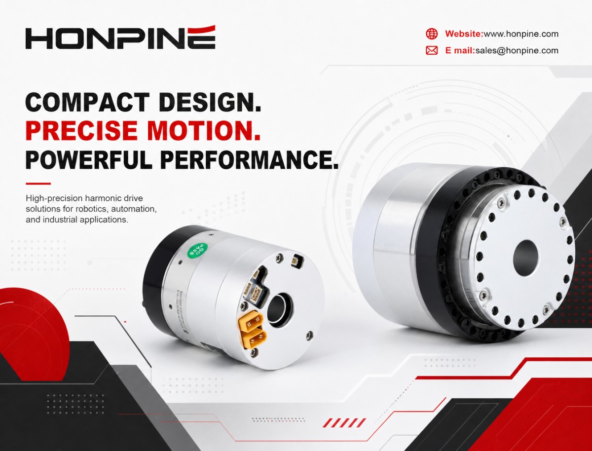
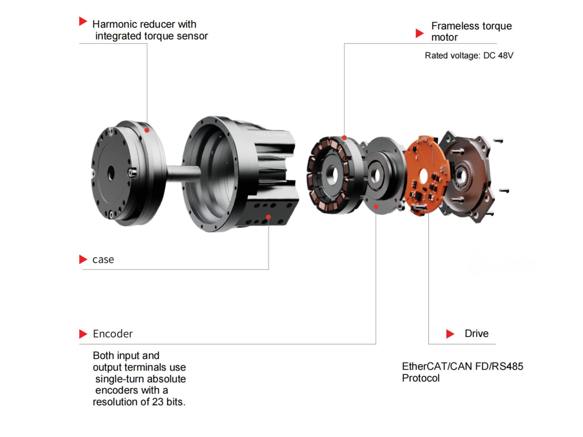
The HPJM module integrates the FOC servo drive board, frameless torque motor, high-precision encoder, harmonic reducer, and crossed roller bearing within a single housing.
Compared with a conventional distributed configuration consisting of a servo motor, an external drive, and a separate reducer, this integrated design eliminates the need for an external drive enclosure, additional mounting brackets, and connecting couplings. It also reduces the installation gaps and alignment requirements between separate components, helping to minimize the overall space occupied by the joint assembly.
Selection tip: First, ensure that the selected module meets the required continuous rated torque and peak torque. Then consider a smaller outer-diameter model where the application allows. Avoid selecting an unnecessarily oversized module simply to provide excessive torque margin. Refer to the product specification tables and compare models with similar output torque. A higher reduction ratio may allow a smaller-diameter module to meet the same output torque requirement, provided that input speed, efficiency, thermal performance, and other operating conditions are also suitable.
Use the Hollow-Shaft Design for Internal Cable Routing
The module features a large central hollow bore that allows power and communication cables to pass directly through the joint.
Instead of routing cables along the outside of the joint, designers can guide them through the hollow center. This helps prevent external cable loops and connectors from increasing the radial dimensions of the assembly.
For robotic arms and humanoid robot limbs with multiple joints connected in series, cables can be routed through the internal passages of successive joints. This reduces the need for external cable channels and protective covers, making the overall structure more compact.
Balance Encoder Configuration Against Space Requirements
The choice of encoder configuration affects both the module's functionality and the space required by peripheral components.
Dual-encoder version (2E): The module includes an output-side feedback encoder and does not require an external 3.6 V multi-turn backup battery. This can eliminate the space needed for a separate battery compartment and mounting bracket. However, the multi-turn position information is not retained after power loss, so the system may need to perform a homing procedure when power is restored.
Single-encoder version: If the selected configuration requires a multi-turn backup battery, the overall robot design must reserve space for the battery and its mounting structure. This option may be suitable for applications that require multi-turn position retention after power loss and have sufficient installation space.
For space-constrained applications, the dual-encoder version may help reduce the number of peripheral components. However, the final choice should also consider position-retention requirements and the robot's control strategy.
Select a Brake Only When the Application Requires It
The module is available in both brake-equipped and brake-free configurations.
If the robot's mechanical structure provides an independent locking mechanism, or if the joint does not need to hold a significant gravitational load when power is removed, a brake-free version may be considered. This can reduce the module's axial length and simplify the installation structure.
If the joint must maintain its position when power is disconnected, a brake-equipped version is generally more appropriate. The required holding torque and safety conditions should be evaluated before making the selection.
2. Optimize Cable Routing: Reduce External Protrusions Through Better Connector and Wiring Layouts
Poor cable routing can create unnecessary protrusions around connectors and cable bends, consuming both radial and axial installation space. This is an easily overlooked issue in compact robot design.
For detailed connector dimensions and wiring requirements, refer to Chapter 4, Electrical Interfaces, and Chapter 7, Cable Routing, in the product manual.
Prioritize Rear-Mounted Board Connectors to Eliminate Adapter Boards
All HPJM models integrate their communication, power, and battery interfaces directly into the motor rear cover through board-mounted connectors. This design does not require an additional external adapter PCB, eliminating the thickness of the adapter board and the space needed for its mounting brackets.
Connector selection:
For modules in the 80–110 mm size range and smaller, the XKB X1002 series of compact connectors with a 1 mm pitch can be used.
Larger modules use compact MOLEX connectors. Compared with XT60 connectors or larger industrial circular connectors, these smaller connectors can help reduce the axial protrusion behind the motor cover.
The actual connector type should be selected according to the module model, current requirements, and interface specifications in the product manual.
Control Cable Direction and Connector Clearance
The cable specification tables in the product manual provide the required clearance heights for different interfaces. When designing the internal cavity of the robot housing, follow these specified clearances rather than unnecessarily increasing the housing dimensions.
For EtherCAT and CAN communication cables, the connectors are unplugged perpendicular to the rear cover. After connection, route the cables along the internal housing cavity and provide sufficient bending space. Avoid allowing cables to bend or protrude radially outward, as this can increase the overall joint diameter.
Power connector selection:
For the compact 30–40 mm module, a 2-pin connector with a 1.25 mm pitch can be used instead of an XT30 connector to reduce the protrusion of the power interface. This is particularly useful when installation space is extremely limited.
For higher-power modules, the XT30UPB-M power socket may be selected where required by the electrical specifications.
Optimize Multi-Module Network Topology to Reduce Redundant Cables
In multi-joint robotic arms and humanoid robot limbs, the network topology has a direct impact on cable quantity and installation space.
EtherCAT communication: Use a daisy-chain connection, with the IN and OUT ports connected sequentially. The main controller needs only one network cable to reach the first joint module, while short cables connect adjacent modules. This avoids routing a separate network cable from every joint back to the controller.
CAN communication: A daisy-chain, or hand-in-hand, bus connection can also be used. Each joint does not need an individual cable routed back to the main controller.
Power supply: A direct power connection to each joint is generally preferable when reliability and voltage stability are priorities. A tree topology may also be considered depending on the electrical architecture. Use a daisy-chain power supply cautiously: although it can reduce cable quantity, voltage drop and current distribution must be carefully evaluated. It is more suitable for lower-power modules when the wiring and power requirements permit it.
For higher-power joints, individual power connections may require more cables but can provide better control over voltage drop and power distribution.
HRoute Cables Through the Hollow Shaft to Eliminate External Cable Channels
Power, CAN, and EtherCAT cables can be routed through the hollow bore of the joint, keeping them inside the mechanical structure.
This reduces the need for external cable channels and protective covers. The external housing can therefore follow the module's motor diameter more closely, without requiring additional radial space for exposed cables.
Important wiring precautions:
Cables must not be pulled taut. Sufficient slack must be provided to accommodate the full range of joint rotation. Even at the mechanical travel limits, cables must not place excessive tension on the connectors.
Foreign objects, protruding cable ties, and other components must also be prevented from pressing against or obstructing the inner wall of the hollow bore.
3. Optimize the Mounting Structure: Minimize Mechanical Installation Gaps
Even when the joint module itself is compact, an inefficient mounting structure can increase the overall dimensions of the robot. Optimizing locating features, fastener arrangements, and the interfaces between adjacent joints helps eliminate unnecessary assembly space.
Use a Locating Pilot to Eliminate Intermediate Adapter Flanges
Where the mechanical design permits, machine a locating pilot directly into the load-side structural component to match the output flange of the joint module. This allows the load-side component to connect directly to the module, eliminating an intermediate adapter flange.
The module's output flange already includes a locating feature. By designing a matching feature into the load-side component, engineers can reduce the axial thickness of the assembly and simplify the mechanical connection.
The locating fit should be specified according to the actual pilot dimensions, tolerances, and assembly requirements. An H7/h7 fit may be considered where appropriate, but it should not be treated as a universal requirement for every joint installation.
The roundness, flatness, and surface condition of the mating surfaces must also be controlled. A flatness tolerance of 0.01 mm may be used as a design target where the application requires it. Avoid applying paint to precision mating surfaces, as coating thickness can affect fit and positioning accuracy.
Use Diagonal Bolt Tightening and Recessed Fastener Holes
Design recessed or countersunk bolt holes in the load-side mounting flange so that bolt heads do not protrude beyond the structural surface. This helps reduce unnecessary axial clearance.
During assembly, tighten the bolts diagonally and follow the specified tightening torque. Medium-strength threadlocker may be used where required by the assembly specification.
Avoid adding unnecessary washers or spacers, as these increase the number of stacked components and the overall installation thickness. However, washers and other fastening elements should not be omitted when they are required by the design or fastener manufacturer's specifications.
The HPJM joint integrates a crossed roller bearing that supports radial and axial loads within its rated capacity. When the integrated bearing can adequately handle the application's external loads and overturning moments, an additional external support bearing is generally unnecessary.
Adding an extra bearing without a clear structural requirement can increase axial and radial dimensions. It may also create an over-constrained mounting arrangement, potentially leading to vibration, abnormal noise, premature wear, or reduced service life.
The external load capacity and mounting arrangement should always be checked against the module's technical specifications before deciding whether additional support is needed.
Keep the Housing Close to the Mounting Surface
The rear cover of the joint module should be positioned as close as practical to the robot housing's mounting surface, while maintaining the minimum clearance required for connectors, cable installation, and maintenance.
The external housing can be designed around the motor's outer diameter to create a compact envelope. Avoid oversized internal cavities or unnecessarily large gaps between the motor housing and the surrounding structural components.
This approach reduces unused space and helps keep the overall robot structure compact.
Avoid Installation Errors That Create Unnecessary Clearance
Several common mounting mistakes can force designers to increase the clearance between components, resulting in wasted installation space.
These include relying only on flat-surface contact without a locating pilot, using an insufficiently deep locating feature, and leaving machining burrs or protrusions on the mating surfaces.
When the locating structure is inadequate, the designer may need to increase the installation gap to avoid interference. This not only increases the overall dimensions but can also compromise assembly consistency.
Before installation, remove burrs and machining debris from the load-side flange. Thoroughly clean all mating surfaces to ensure that the components fit together properly.
Arrange Multiple Joints in a Compact Series Configuration
For multi-joint structures such as humanoid robot arms and legs, a compact series arrangement can help reduce the overall limb length.
Where the mechanical interface permits, connect the output flange of one joint directly to the rear cover or mounting interface of the next joint. Eliminate unnecessary intermediate spacers and adapter structures, while retaining the minimum clearance required for cable bending and assembly.
If the hollow bores of the connected modules are aligned, cables can pass through successive joints along the internal route. This reduces external cable routing and helps achieve a more compact overall limb structure.
Conclusion
Achieving high torque in a compact space is not simply a matter of selecting a smaller robot joint module. It requires coordinated optimization of the module's internal architecture, encoder and brake configuration, connector selection, cable routing, mounting interfaces, and multi-joint arrangement.
The HONPINE HPJM integrated robot joint modulecombines key motion-control components within a compact housing. By making full use of its integrated structure and hollow-shaft design, and by optimizing the surrounding mechanical and electrical layout, robot manufacturers can reduce unnecessary installation space while meeting their torque and motion-control requirements.
For humanoid robots, robotic arms, and other multi-joint systems, effective space optimization begins at the module selection stage and continues throughout the mechanical and electrical design process.
Read More
Learn more about the story of HONPINE and industry trends related to precision transmission.
 What is robot joint actuator?How to Choose the Best Robot Rotary Joint Actuator?In core robot joint transmission solutions, planetary and harmonic rotary actuators each have their own strengths. Choosing the right type based on application requirements is essential to achieve the optimal balance between performance and cost.
 DD Motors VS Harmonic Rotary ActuatorsThis article provides an in-depth comparison between Direct Drive (DD) motors and harmonic rotary actuators, covering their transmission principles, advantages and disadvantages, and typical application fields.
 OMG Ultra Compact Harmonic Drive Joint Module with Built-in Torque SensorHONPINE TCHL series harmonic drive joint module is a game-changing product that achieves disruptive improvements in multiple aspects such as lightweight design, integration level, and connection convenience. This article will analyze its revolutionary enhancements with you.
 The Role of Harmonic Drive Gears in Achieving 5–10 μm Accuracy in Dental Milling MachinesA dental milling machine is a CNC machining system used to directly process digital dental models into restorations such as crowns, bridges, veneers, inlays, and implant abutments. Dental milling machines require far higher operational accuracy and motion stability than ordinary equipment. This article explains how harmonic drive gear help dental milling machines achieve stable, continuous, and controllable operation.
 Why Are Harmonic Rotary Actuators Perfect for Medical Equipment?Harmonic rotary actuators (typically integrated systems consisting of a harmonic drive reducer, frameless torque motor, encoder, and optional brake) are regarded as key components in medical equipment. The core reason is that they simultaneously meet the most stringent medical requirements for precision, compact size, safety, and controllability. The following explanation is structured from three perspectives: technical characteristics, application scenarios, and medical value.
 High-Precision RV Reducers Perfectly Matched for Walking RobotsThe walking axis of a robot is a core component for power transmission and support. RV reducers provide extremely high rigidity, precision, and torque while maintaining a compact size and exceptional reliability, making them an ideal match for the demanding requirements of walking robot joints in terms of load capacity, impact resistance, and precision.
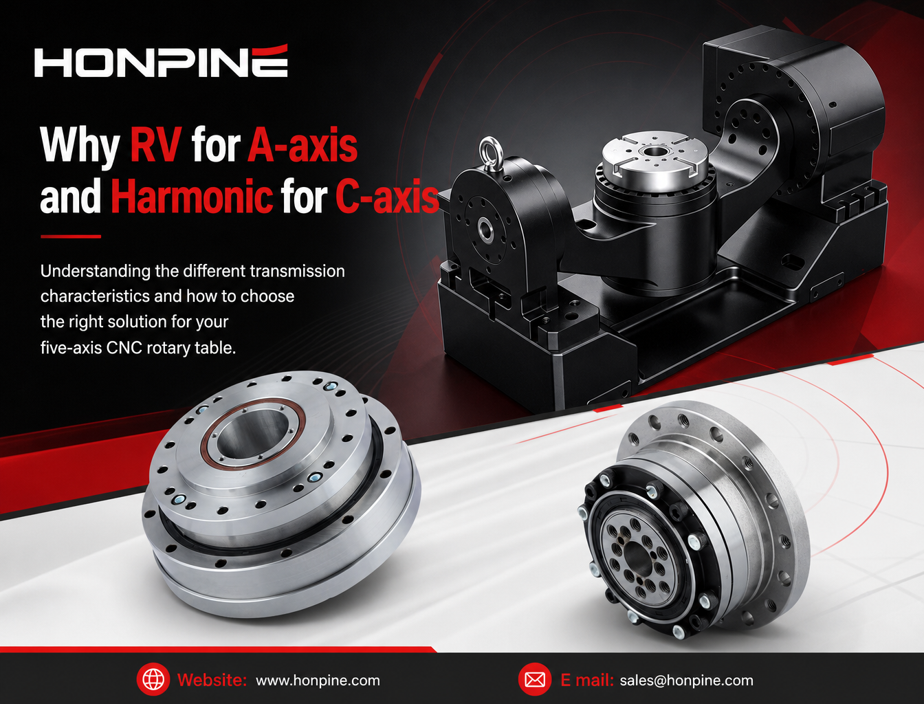
 Why Do Five-Axis CNC Rotary Tables Use Different Reducers for the A-Axis and C-Axis?Five-axis CNC rotary tables require different transmission characteristics for the A-axis and C-axis. While the A-axis often needs high torsional stiffness and load-bearing capacity to support the cradle assembly and workpiece, the C-axis places greater emphasis on low backlash, angular positioning accuracy, and dynamic response. This article explains why RV reducers are often considered for A-axis applications and harmonic reducers for C-axis applications, covering their working principles, mechanical advantages, output-side feedback, and key selection criteria for CNC machine tool manufacturers.
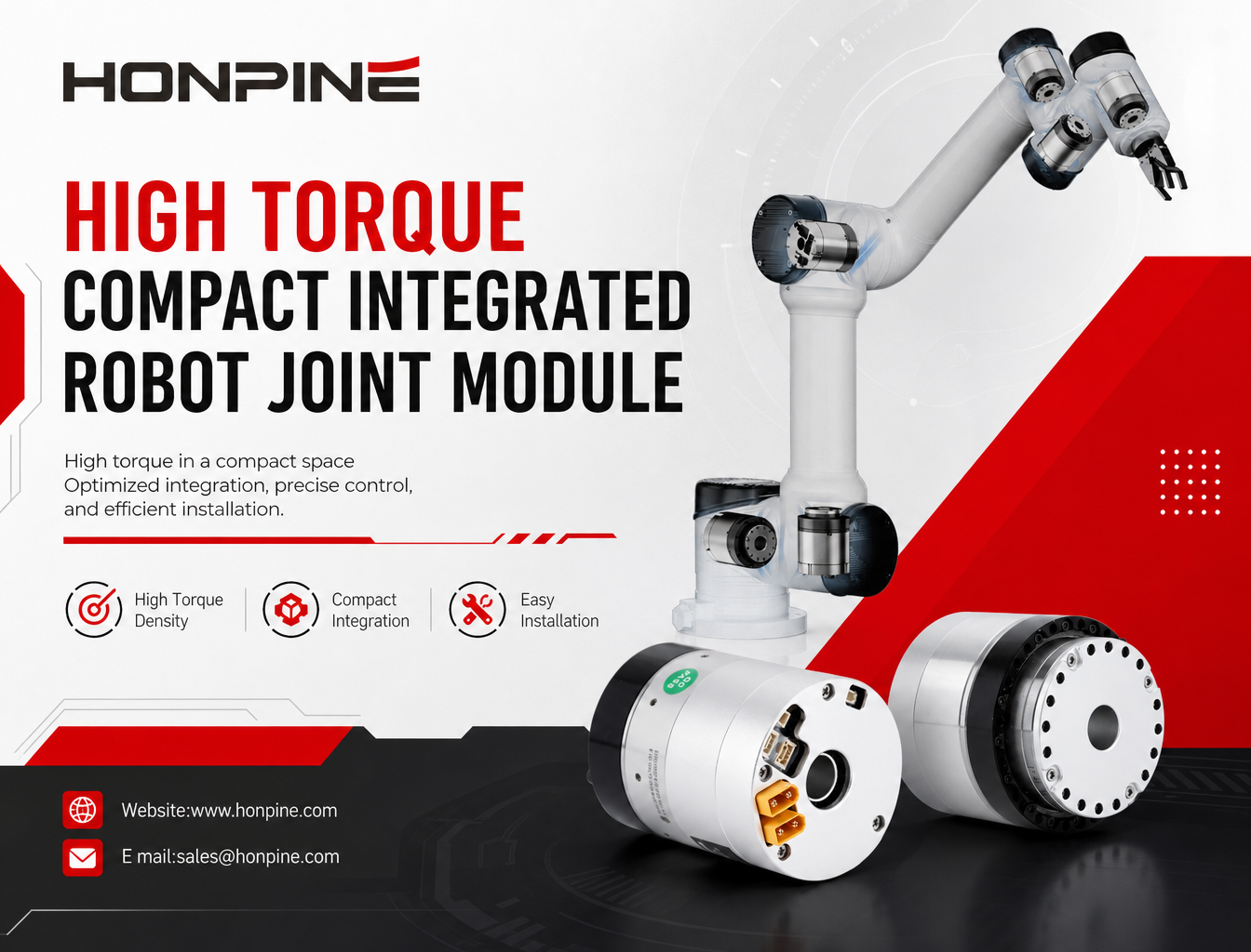
 How Does the HONPINE HPJM Integrated Robot Joint Module Deliver High Torque in a Compact Space?Learn how to optimize installation space while achieving high torque density in robotic joints. This article explores how the HONPINE HPJM integrated robot joint module uses integrated components, hollow-shaft cable routing, compact electrical connectors, and optimized mechanical mounting structures to reduce unnecessary space in humanoid robots and robotic arms.
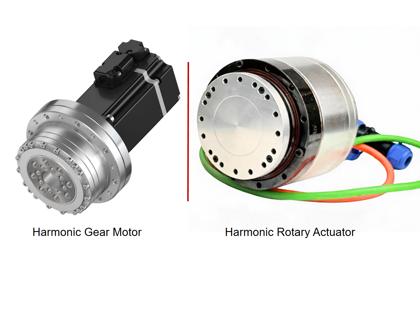
 Harmonic Gear Motor vs. Harmonic Actuator: What Are the Differences?This article explains the differences between harmonic gear motors and harmonic actuators from the perspectives of product design, system integration, feedback and control functions, installation, and application requirements. Since manufacturers may use these product names differently, it also explores how to evaluate their actual configurations and select the right precision motion solution for robotics and industrial automation.
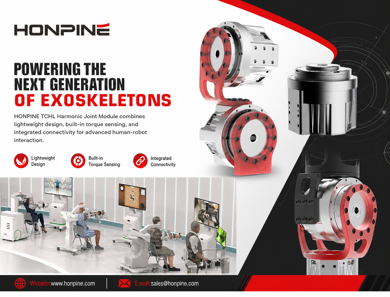
 Why Is the HONPINE TCHL Harmonic Joint Module Suitable for Exoskeleton Robots?The HONPINE TCHL Harmonic Joint Module is designed for exoskeleton robots that require lightweight construction, compact mechanical integration, and responsive human-robot interaction. Featuring a built-in output-side torque sensor, a highly integrated structure, and flexible connection configurations, the TCHL provides a joint drive solution for lower-limb exoskeletons, upper-limb assistive robots, rehabilitation equipment, and industrial wearable robots.
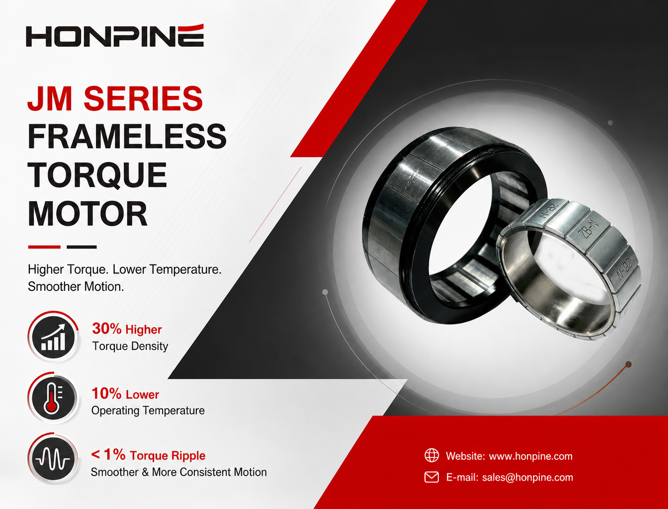
 HONPINE JM Fourth-Generation Frameless Torque Motor: 30% Higher Torque Density and 10% Lower Operating TemperatureAs robotics technology advances, frameless torque motors are facing increasingly demanding requirements for torque density, motion stability, and thermal management. The HONPINE JM fourth-generation frameless torque motor achieves 30% higher torque density and 10% lower operating temperature through improvements in electromagnetic design, core materials, and winding technology. With torque ripple controlled below 1%, it delivers smoother low-speed operation and improved motion consistency, making it suitable for demanding applications such as surgical robots, humanoid robots, and precision automation equipment. How does HONPINE achieve these performance improvements? Let's take a closer look.
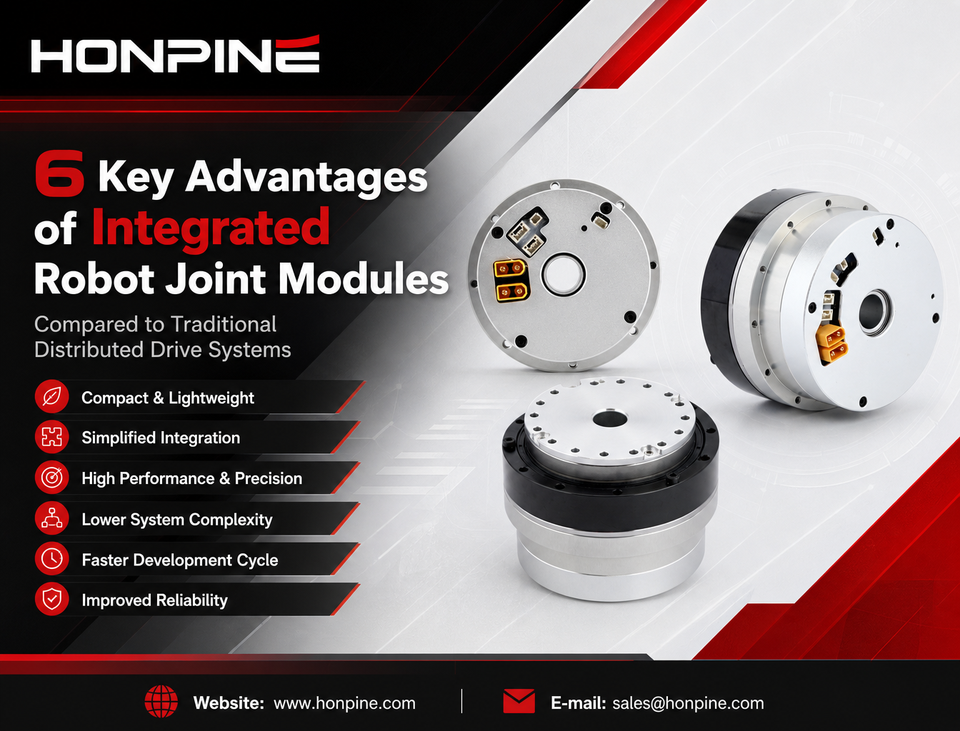
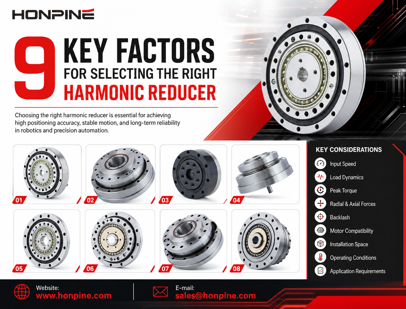
 How to Select a Harmonic Reducer: 9 Key Factors You Need to KnowWhy are more robotics companies choosing integrated robot joint modules instead of traditional distributed drive systems? As humanoid robots, collaborative robots, and rehabilitation exoskeletons continue to evolve, manufacturers are looking for more compact, lightweight, and easier-to-integrate motion solutions. An integrated robot joint module combines essential components such as a frameless torque motor, harmonic reducer, servo drive, encoders, and output bearing into a single assembly. This architecture can reduce mechanical complexity, simplify wiring, improve motion control integration, and shorten robot development cycles. In this article, Theodore Li, Technical Director at HONPINE, explains six key advantages of integrated robot joint modules and compares them with conventional distributed drive configurations.
Double Click
We provide harmonic drive reducer,planetary reducer,robot joint motor,robot rotary actuators,RV gear reducer,robot end effector,dexterous robot hand
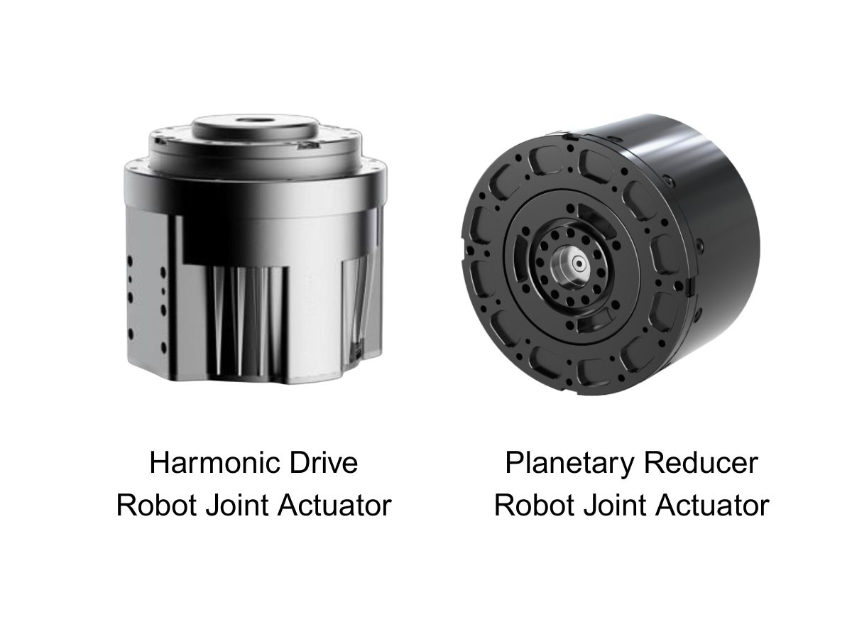
 What is robot joint actuator?How to Choose the Best Robot Rotary Joint Actuator?In core robot joint transmission solutions, planetary and harmonic rotary actuators each have their own strengths. Choosing the right type based on application requirements is essential to achieve the optimal balance between performance and cost.
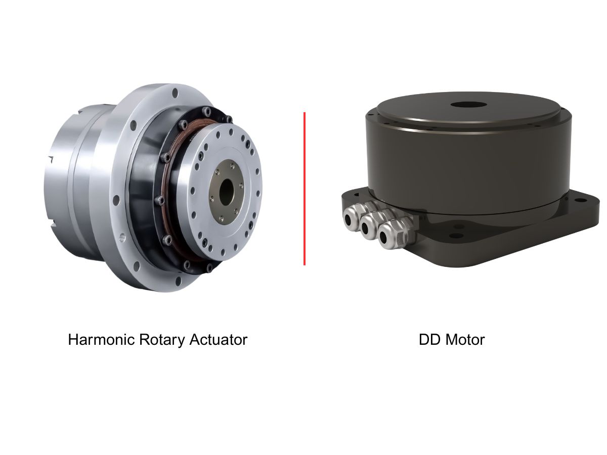
 DD Motors VS Harmonic Rotary ActuatorsThis article provides an in-depth comparison between Direct Drive (DD) motors and harmonic rotary actuators, covering their transmission principles, advantages and disadvantages, and typical application fields.
 OMG Ultra Compact Harmonic Drive Joint Module with Built-in Torque SensorHONPINE TCHL series harmonic drive joint module is a game-changing product that achieves disruptive improvements in multiple aspects such as lightweight design, integration level, and connection convenience. This article will analyze its revolutionary enhancements with you.
 Why Do Five-Axis CNC Rotary Tables Use Different Reducers for the A-Axis and C-Axis?Five-axis CNC rotary tables require different transmission characteristics for the A-axis and C-axis. While the A-axis often needs high torsional stiffness and load-bearing capacity to support the cradle assembly and workpiece, the C-axis places greater emphasis on low backlash, angular positioning accuracy, and dynamic response. This article explains why RV reducers are often considered for A-axis applications and harmonic reducers for C-axis applications, covering their working principles, mechanical advantages, output-side feedback, and key selection criteria for CNC machine tool manufacturers.
 How Does the HONPINE HPJM Integrated Robot Joint Module Deliver High Torque in a Compact Space?Learn how to optimize installation space while achieving high torque density in robotic joints. This article explores how the HONPINE HPJM integrated robot joint module uses integrated components, hollow-shaft cable routing, compact electrical connectors, and optimized mechanical mounting structures to reduce unnecessary space in humanoid robots and robotic arms.
 Harmonic Gear Motor vs. Harmonic Actuator: What Are the Differences?This article explains the differences between harmonic gear motors and harmonic actuators from the perspectives of product design, system integration, feedback and control functions, installation, and application requirements. Since manufacturers may use these product names differently, it also explores how to evaluate their actual configurations and select the right precision motion solution for robotics and industrial automation.
 HONPINE JM Fourth-Generation Frameless Torque Motor: 30% Higher Torque Density and 10% Lower Operating TemperatureAs robotics technology advances, frameless torque motors are facing increasingly demanding requirements for torque density, motion stability, and thermal management. The HONPINE JM fourth-generation frameless torque motor achieves 30% higher torque density and 10% lower operating temperature through improvements in electromagnetic design, core materials, and winding technology. With torque ripple controlled below 1%, it delivers smoother low-speed operation and improved motion consistency, making it suitable for demanding applications such as surgical robots, humanoid robots, and precision automation equipment. How does HONPINE achieve these performance improvements? Let's take a closer look.
 How to Select a Harmonic Reducer: 9 Key Factors You Need to KnowWhy are more robotics companies choosing integrated robot joint modules instead of traditional distributed drive systems? As humanoid robots, collaborative robots, and rehabilitation exoskeletons continue to evolve, manufacturers are looking for more compact, lightweight, and easier-to-integrate motion solutions. An integrated robot joint module combines essential components such as a frameless torque motor, harmonic reducer, servo drive, encoders, and output bearing into a single assembly. This architecture can reduce mechanical complexity, simplify wiring, improve motion control integration, and shorten robot development cycles. In this article, Theodore Li, Technical Director at HONPINE, explains six key advantages of integrated robot joint modules and compares them with conventional distributed drive configurations.
 Why Are More Companies Choosing Integrated Robot Joint Modules?Integrated robot joint modules combine motors, harmonic reducers, servo drives, encoders, and output bearings into compact units. This article compares integrated and distributed drive architectures, exploring their differences in torque density, mechanical reliability, motion control, development efficiency, and practical robotic applications.
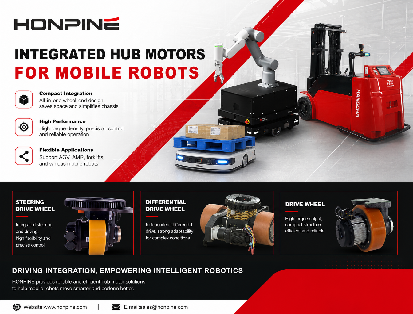
 Why Are More Robots Moving Away from Traditional Drive Systems to Integrated Hub Servo Motors?As mobile robots evolve toward autonomous navigation, flexible operation, and increasingly complex working environments, traditional distributed drive systems are facing new challenges. Separate motors, gearboxes, couplings, and transmission components can increase chassis complexity and limit available installation space. This is why more robot manufacturers are turning to integrated hub servo motors. By combining key drive components within a compact wheel-end unit, hub motors offer new possibilities for improving drive integration, motion control, and chassis design. In this article, we explore the key performance requirements of mobile robots, explain the advantages of integrated hub motors, and examine how HONPINE's Drive Wheels, Steering Drive Wheels, and Differential Drive Wheels support different AGV and AMR applications.
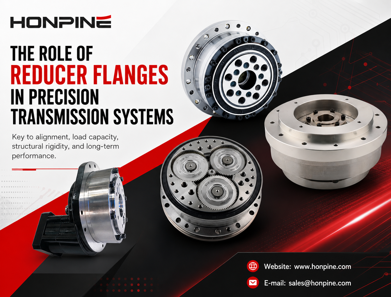
 Why Are Flanges on Harmonic and RV Reducers More Than Just Mechanical Mounting Components?A flange on a harmonic reducer or RV reducer is more than a mounting interface. It plays a critical role in alignment accuracy, load transmission, structural stiffness, and sealing performance. Even minor errors in flange design or installation can affect gear meshing, bearing life, and the overall reliability of a precision motion system. In this article, Theodore Li, Technical Director at HONPINE, explains the key engineering functions of reducer flanges and why they deserve careful consideration when designing and installing precision transmission systems.
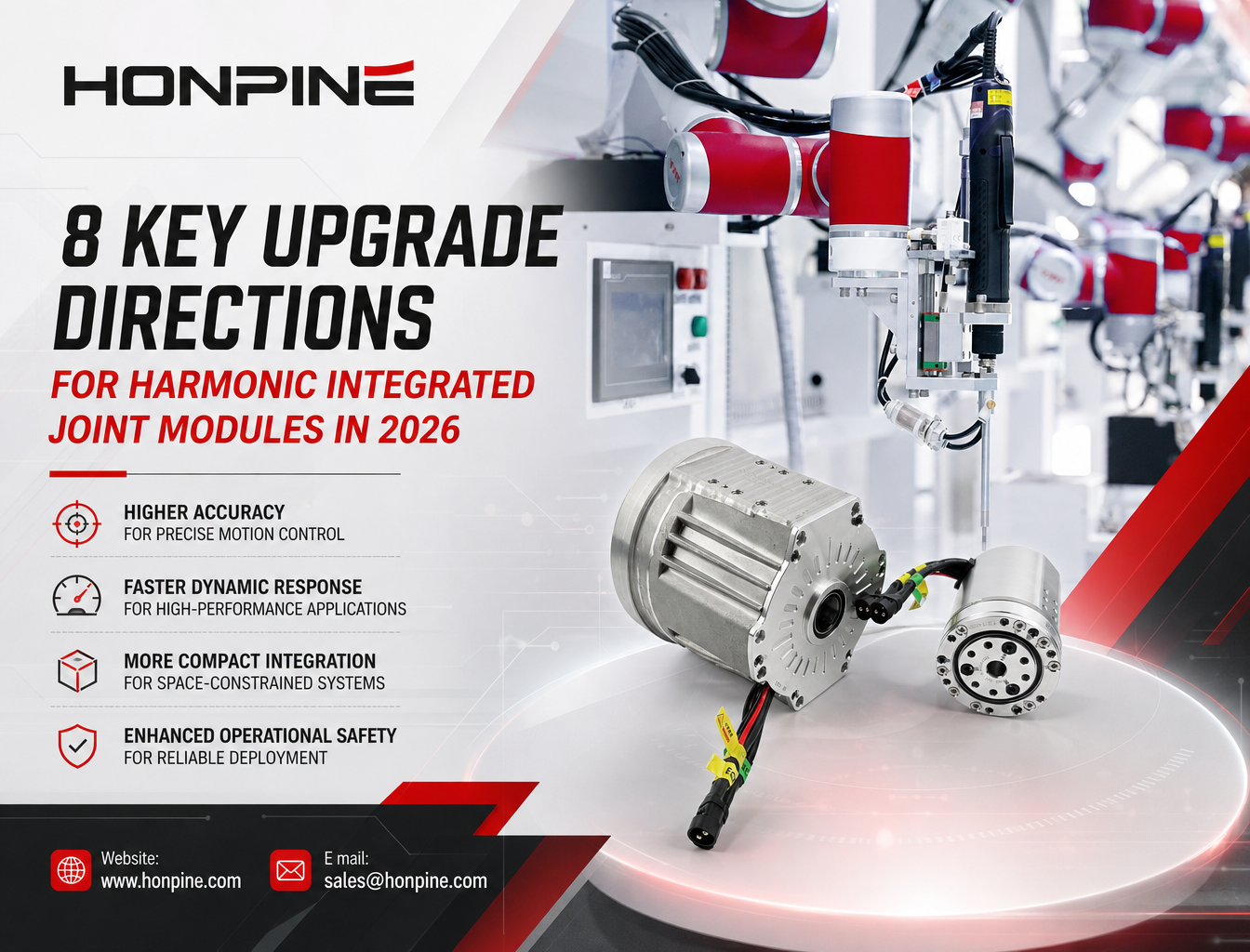
 How Should Manufacturers Upgrade Harmonic Joint Modules for Robotic Arms and Embodied AI in 2026?For engineers planning a robotic system upgrade, the right joint module depends on more than a single specification. EtherCAT synchronization, output-side position feedback, real-time torque measurement, continuous torque capability, and integrated safety functions must work together to meet the demands of the application. By evaluating these factors as a complete electromechanical system, manufacturers can make more informed decisions about joint module selection, integration, and long-term performance.