








How to Choose a Hollow Rotary Platform: A Complete Selection Guide?
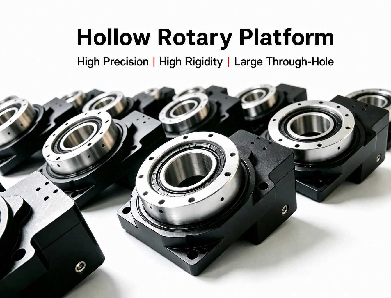
A Hollow Rotary Platform is a precision rotary component commonly used in automated positioning, indexing, inspection, laser processing, dispensing, and other motion-control applications. Compared with conventional rotary mechanisms, its hollow center allows cables, air lines, optical fibers, and other utilities to pass directly through the rotation axis, making it easier to achieve a compact and integrated machine design.
Depending on the transmission structure and application requirements, a hollow rotary mechanism may also be referred to as a Hollow Rotary Table or Hollow Rotary Actuator. Although these products may look similar from the outside, their load capacity, positioning accuracy, hollow bore, speed, rigidity, and motor configuration can vary significantly.
For this reason, selecting a hollow rotary platform should not be based on a single parameter such as rated torque or maximum speed. A proper selection needs to consider the actual load, eccentricity, inertia, precision requirements, hollow bore, acceleration, duty cycle, installation orientation, and operating environment.
What Should You Consider When Selecting a Hollow Rotary Platform?
In practical applications, a useful selection sequence is:
Load and overturning moment → Load inertia → Positioning and rotational accuracy → Hollow bore → Speed and acceleration → Motor matching → Installation and environment → Safety margin
This sequence helps prevent a common problem: selecting a rotary platform based on nominal specifications while overlooking the actual operating conditions of the machine.
1. Start With the Actual Operating Conditions
Before comparing different Hollow Rotary Table models, first define how the rotary mechanism will actually work.
The basic parameters should include:
Total payload, fixture, and workpiece weight
Distance between the center of gravity and the rotation axis
Required output torque
Axial and radial loads
Maximum rotational speed
Acceleration and deceleration
Number of start-stop cycles
Required positioning accuracy
Required repeatability
Required hollow bore diameter
Installation orientation
Operating environment
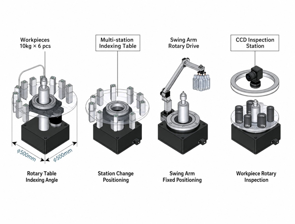
For example, a rotary table carrying a 10 kg workpiece with its center of gravity close to the rotation axis can have completely different mechanical requirements from a 10 kg workpiece mounted 100 mm away from the axis.
The weight is the same, but the overturning moment is different.
2. Check Rated Torque and Peak Torque
Torque is one of the first parameters engineers normally check when selecting a Hollow Rotary Platform, but rated torque and peak torque should be understood separately.
Rated torque generally relates to the torque that the rotary mechanism can continuously handle under specified operating conditions.
Peak torque is more relevant to short-duration acceleration, deceleration, startup, or impact loads.
For continuous resistance loads, the required torque should remain within the rated torque range. During acceleration or sudden changes in motion, the instantaneous torque may approach the peak torque capability.
However, torque alone is not enough.
The mechanical load may also generate axial force, radial force, and overturning moment. Therefore, the load capacity of the complete Hollow Rotary Actuator should be checked rather than selecting a model only according to its nominal output torque.
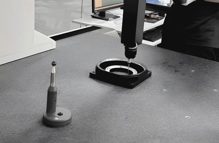
3. Pay Attention to Eccentric Load and Overturning Moment
Eccentric loading is one of the most frequently overlooked factors in rotary platform selection.
When the center of gravity of the workpiece or fixture is offset from the rotation axis, it generates an overturning moment.
The basic calculation is:
M = F × L
Where:
M = overturning moment
F = load force
L = distance from the load center to the rotation axis
For example, if a 10 kg load is positioned 100 mm from the rotation axis:
F ≈ 10 × 9.81 = 98.1 N
M ≈ 98.1 × 0.1 = 9.81 N·m
This is why two applications with the same payload weight may require completely different rotary platforms.
For applications involving large eccentric loads, rapid acceleration, or external impact, engineers should also leave an appropriate mechanical safety margin rather than selecting a platform close to its theoretical limit.
4. Calculate Load Inertia, Not Just Load Weight
Load weight determines the basic mechanical load, but rotational inertia determines how difficult it is to accelerate and decelerate the load.
For a simplified disk-shaped load:
J = 1/2 × m × r²
Where:
J = moment of inertia
m = mass
r = rotational radius
The actual inertia calculation should consider the geometry of the workpiece, fixture, rotary platform, and other rotating components.
For a reduction-type rotary mechanism, the load inertia can also be converted to the motor side according to the reduction ratio. In simplified form:
J_motor-side = J_load / i²
Where i is the reduction ratio.
The resulting motor-side load inertia should then be compared with the motor rotor inertia.
Why Does Inertia Matching Matter?
If the load inertia is excessively high relative to the motor inertia, the system may experience:
Longer acceleration and deceleration time
Increased positioning deviation
Vibration during startup or stopping
Servo following errors
Motor overload
Difficulty in achieving the required cycle time
An inertia ratio such as load inertia / motor rotor inertia < 5 can be used as an engineering reference in some servo applications, but it should not be treated as a universal standard.
The acceptable inertia ratio depends on the motor, drive, control algorithm, reduction mechanism, acceleration profile, and actual duty cycle.
For a Hollow Rotary Actuator used in a high-speed, frequently accelerating servo system, inertia matching generally deserves more attention than in a low-speed indexing application.
5. Understand the Difference Between Positioning Repeatability and Rotational Accuracy
Precision is another important selection factor, but several different parameters are often confused.
Repeat Positioning Accuracy
Repeat positioning accuracy describes how consistently the rotary platform can return to the same position.
This is particularly important for:
Vision inspection
Automated assembly
Dispensing
Laser processing
Indexing applications
Precision positioning
Backlash
Backlash refers to the mechanical clearance or lost motion that can occur when the rotation direction changes.
Low backlash is particularly important for applications involving frequent bidirectional positioning.
For applications where the platform rotates primarily in one direction, backlash may have a different impact on system performance.
Radial and Axial Runout
For precision fixtures, inspection systems, and optical applications, face runout and radial runout can be just as important as positioning repeatability.
Therefore, when comparing different Hollow Rotary Tables, do not look at only one accuracy specification. The complete mechanical accuracy requirements of the application should be considered.
6. Select the Hollow Bore According to the Actual Routing Requirements
The hollow structure is one of the major advantages of a Hollow Rotary Platform.
The center bore can provide a routing path for:
Motor cables
Encoder cables
Pneumatic tubing
Vacuum lines
Optical fibers
Sensor wiring
Cooling lines
However, choosing the largest possible hollow bore is not always the best solution.
A larger bore can increase the external dimensions, structural size, weight, and cost of the rotary mechanism.
When selecting the bore diameter, consider not only the current cable bundle but also:
Connector dimensions
Cable bending radius
Pneumatic fitting size
Future wiring requirements
Maintenance space
Installation clearance
The goal is to provide sufficient internal routing space without unnecessarily increasing the size of the entire rotary assembly.
7. Check Speed, Acceleration, and Deceleration
Maximum speed is another important parameter, but it should always be evaluated together with acceleration and duty cycle.
A rotary platform may be technically capable of reaching a certain maximum speed, but that does not necessarily mean it should operate continuously at that speed under a heavy load.
For indexing applications, the key parameters may be:
Rotation angle
Indexing time
Acceleration time
Deceleration time
Dwell time
Number of cycles per minute
For continuous rotation, thermal performance and torque derating should also be considered.
When acceleration and deceleration are too aggressive, the system may experience vibration, mechanical shock, abnormal noise, or reduced positioning stability.
Increasing the acceleration and deceleration time can sometimes improve the overall motion performance without changing the rotary platform itself.
8. Distinguish Between Intermittent and Continuous Operation
Many Hollow Rotary Platforms are particularly suitable for intermittent indexing and positioning.
Typical applications include:
CNC indexing
Assembly stations
Vision inspection
Laser marking
Dispensing
Multi-station automation
These applications often require rapid positioning followed by a stationary period.
Continuous rotation is different.
If the platform needs to rotate continuously for long periods, engineers should evaluate:
Continuous torque
Bearing speed
Motor heating
Gearbox efficiency
Lubrication
Thermal dissipation
Duty cycle
The same rotary platform may have different allowable performance depending on whether it operates intermittently or continuously.
9. Match the Hollow Rotary Platform With the Motor
For a motor-driven rotary mechanism, the motor and transmission should be considered as one motion system.
The basic matching parameters include:
Required motor torque
Required motor speed
Motor rotor inertia
Reduction ratio
Output torque
Acceleration requirements
Motor flange
Shaft or coupling interface
Encoder configuration
Installation orientation
The required motor torque should be calculated from the actual load and reduction ratio rather than simply selecting a motor based on the output torque of the platform.
For applications requiring compact integration, a Hollow Rotary Actuator with an integrated motor, encoder, and transmission can reduce the number of external mechanical components and simplify system integration.
10. Consider Installation Orientation
Installation orientation can affect the actual load on the rotary mechanism.
Horizontal installation is common for rotary tables, but vertical installation may introduce additional axial loading or change the direction of the gravitational load.
Before selecting a model, confirm:
Horizontal or vertical installation
Direction of gravitational load
Axial load
Radial load
External overturning moment
Fixture mounting structure
Output flange rigidity
For vertical applications, the mechanical structure must be capable of supporting the load safely even when the drive system is powered down.
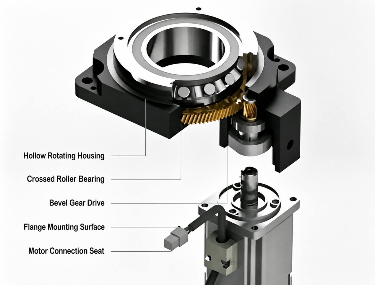
11. Consider the Operating Environment
The operating environment can directly affect the service life and reliability of a rotary platform.
For applications involving dust, chips, coolant, or other contaminants, check the required protection level and sealing structure.
Typical environmental factors include:
Dust and debris
Cutting fluid
Humidity
Temperature
Corrosive substances
Vibration
Frequent start-stop operation
For humid or corrosive environments, surface treatment and corrosion protection may also need to be considered.
If the application involves frequent start-stop cycles, especially more than 20 cycles per minute, bearing life and thermal conditions should be evaluated rather than relying only on the nominal rated life.
12. Check Bearing Rigidity and Service Life
The transmission system is not the only factor that determines the performance of a Hollow Rotary Table.
The bearing structure also affects:
Radial rigidity
Axial rigidity
Tilt rigidity
Runout
Load capacity
Service life
For applications with large eccentric loads or high precision requirements, bearing rigidity becomes particularly important.
A platform with sufficient torque but insufficient mechanical rigidity may still experience deflection or positioning errors under load.
Therefore, the complete mechanical structure should be evaluated rather than comparing gear ratio or motor torque alone.
13. Leave an Appropriate Safety Margin
Selecting a rotary platform exactly at the calculated load limit is generally not advisable.
The required safety margin depends on the actual application.
For relatively stable intermittent loads, an engineering margin of approximately 1.2–1.5× can be used as a preliminary reference.
For applications involving shock loads, large eccentricity, or frequent acceleration and deceleration, a larger margin such as 1.5–2× may be appropriate.
These values should be treated as engineering references rather than universal standards. The final selection should be verified against the manufacturer's load, torque, bearing, speed, and duty-cycle specifications.
14. Hollow Rotary Platform Selection Checklist
Before selecting a model, it is useful to prepare the following information:
With these parameters available, it becomes much easier to compare different Hollow Rotary Platform and Hollow Rotary Actuator configurations.
15. Different Applications Require Different Selection Priorities
There is no single specification that determines whether a rotary platform is suitable for every application.
For high-precision applications, a Hollow Rotary Actuator can provide a more integrated solution when the motor, transmission, encoder, and output mechanism need to work together as a complete motion system.
16. Common Mistakes When Selecting a Hollow Rotary Platform
Only Looking at Rated Torque
A platform may have sufficient rated torque but still be unsuitable because of excessive eccentric load, inertia, or axial/radial loading.
Selecting Based Only on Payload Weight
Two loads with the same mass can generate very different overturning moments depending on their distance from the rotation axis.
Treating Inertia Ratio as a Fixed Number
An inertia ratio of 5 is sometimes used as an engineering reference, but the appropriate value depends on the motor, servo drive, acceleration, and control system.
Looking Only at Positioning Accuracy
Repeat positioning accuracy, backlash, runout, rigidity, and vibration are different performance indicators.
Choosing the Largest Hollow Bore
A larger bore provides more routing space, but it can also increase the size and cost of the complete rotary mechanism.
Ignoring Duty Cycle
A rotary platform used for occasional indexing has different thermal and bearing requirements from one operating continuously at high speed.
Ignoring Installation Orientation
Vertical installation can introduce different axial and gravitational loads compared with horizontal installation.
How to Select the Right Hollow Rotary Platform?
The selection of a Hollow Rotary Platform should start with the actual mechanical conditions rather than a single catalog parameter.
First determine the total load and eccentricity, then calculate the overturning moment and rotational inertia. After that, evaluate positioning accuracy, repeatability, backlash, runout, hollow bore, speed, acceleration, and duty cycle.
For systems requiring a more integrated motion solution, a Hollow Rotary Actuator can combine the transmission mechanism, motor, encoder, and output structure into a compact rotary unit. This can simplify mechanical integration while providing a cleaner solution for automated rotary motion.
For applications such as CNC indexing, wafer handling, vision inspection, laser processing, dispensing, panel handling, and precision positioning, the appropriate solution should ultimately be selected according to the complete load, precision, speed, structural, and environmental requirements of the machine.
A practical selection sequence is therefore:
Overturning moment → Load torque → Load inertia → Precision → Hollow bore → Speed and acceleration → Motor matching → Installation and environment → Safety margin
This approach provides a more reliable basis for selecting the appropriate Hollow Rotary Platform, Hollow Rotary Table, or Hollow Rotary Actuator for the application.
Read More
Learn more about the story of HONPINE and industry trends related to precision transmission.
 What is robot joint actuator?How to Choose the Best Robot Rotary Joint Actuator?In core robot joint transmission solutions, planetary and harmonic rotary actuators each have their own strengths. Choosing the right type based on application requirements is essential to achieve the optimal balance between performance and cost.
 DD Motors VS Harmonic Rotary ActuatorsThis article provides an in-depth comparison between Direct Drive (DD) motors and harmonic rotary actuators, covering their transmission principles, advantages and disadvantages, and typical application fields.
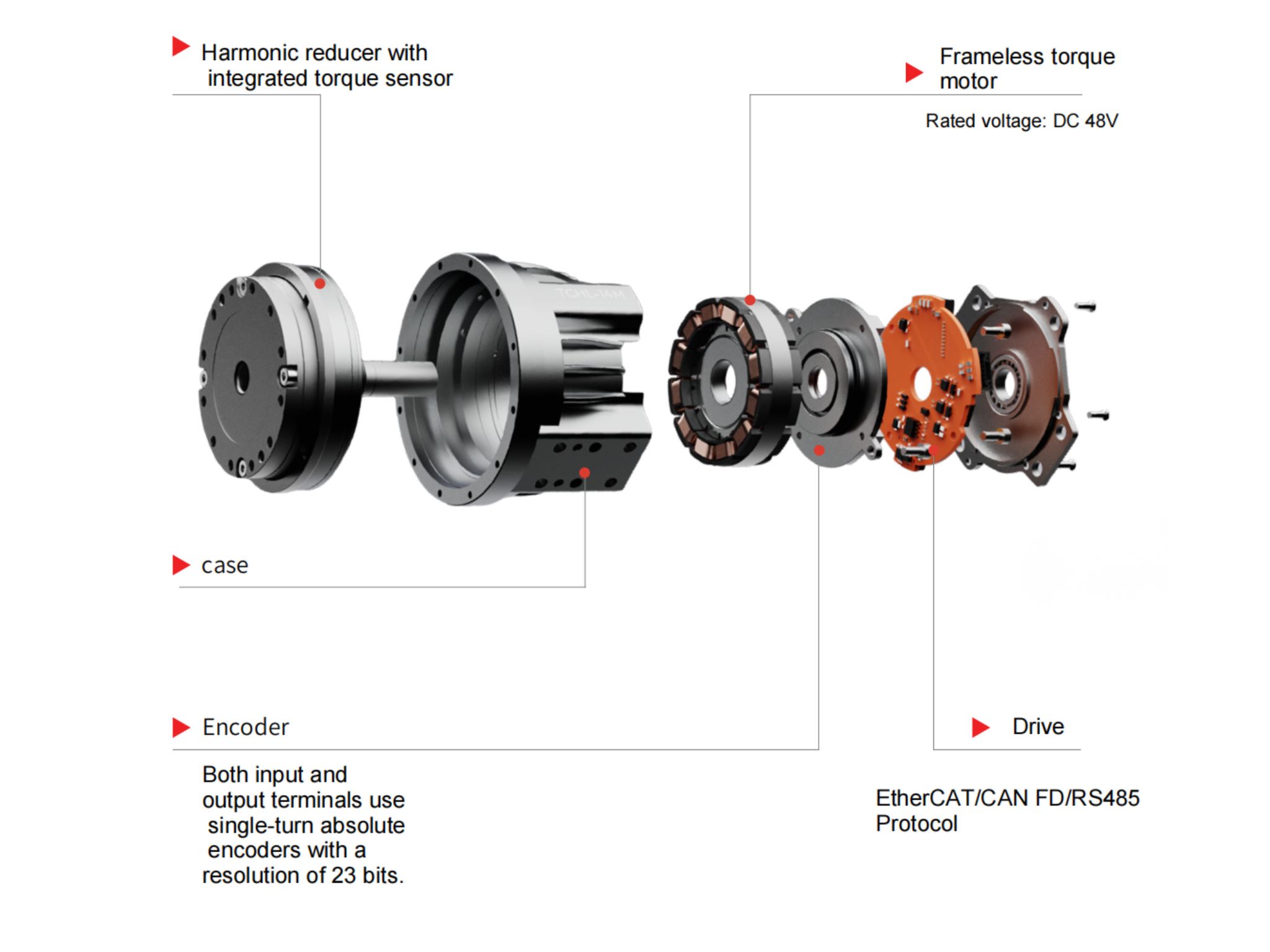
 OMG Ultra Compact Harmonic Drive Joint Module with Built-in Torque SensorHONPINE TCHL series harmonic drive joint module is a game-changing product that achieves disruptive improvements in multiple aspects such as lightweight design, integration level, and connection convenience. This article will analyze its revolutionary enhancements with you.
 The Role of Harmonic Drive Gears in Achieving 5–10 μm Accuracy in Dental Milling MachinesA dental milling machine is a CNC machining system used to directly process digital dental models into restorations such as crowns, bridges, veneers, inlays, and implant abutments. Dental milling machines require far higher operational accuracy and motion stability than ordinary equipment. This article explains how harmonic drive gear help dental milling machines achieve stable, continuous, and controllable operation.
 Why Are Harmonic Rotary Actuators Perfect for Medical Equipment?Harmonic rotary actuators (typically integrated systems consisting of a harmonic drive reducer, frameless torque motor, encoder, and optional brake) are regarded as key components in medical equipment. The core reason is that they simultaneously meet the most stringent medical requirements for precision, compact size, safety, and controllability. The following explanation is structured from three perspectives: technical characteristics, application scenarios, and medical value.
 High-Precision RV Reducers Perfectly Matched for Walking RobotsThe walking axis of a robot is a core component for power transmission and support. RV reducers provide extremely high rigidity, precision, and torque while maintaining a compact size and exceptional reliability, making them an ideal match for the demanding requirements of walking robot joints in terms of load capacity, impact resistance, and precision.
 Why Does an RV Reducer Need Profile Modification? How to Further Reduce Backlash and Transmission Error?An RV Reducer is designed to deliver high torque, high stiffness, and precise motion for demanding applications such as robotic joints, industrial rotary tables, and precision machinery. However, achieving low backlash and stable transmission accuracy requires more than high-precision machining. Cycloidal profile modification must also account for manufacturing tolerances, assembly errors, load-induced deformation, thermal expansion, and lubrication conditions. In this article, we examine why RV reducers require profile modification, how different modification methods affect meshing, and how engineers can further control backlash and transmission error through profile design, error budgeting, structural analysis, precision manufacturing, and validation testing.
 How to Choose a Hollow Rotary Platform: A Complete Selection Guide?A hollow rotary platform is widely used in precision automation where rotary positioning, compact integration, and cable routing through the rotation axis are required. However, choosing the right platform involves more than comparing rated torque or maximum speed. Load, eccentricity, overturning moment, inertia, positioning accuracy, hollow bore, acceleration, duty cycle, and installation conditions all affect the actual performance of the rotary system. This guide explains the key parameters engineers should consider when selecting a hollow rotary platform for CNC indexing, wafer handling, vision inspection, laser processing, dispensing, and other precision rotary applications.
 Hollow Robot Joint Module: Why Cable Routing Matters in Robotic Joints?A hollow robot joint module provides an internal passage for power cables, signal lines, pneumatic tubes, and other end-effector connections. Compared with external cable routing, a hollow joint module can help reduce cable exposure, improve system integration, and create a cleaner motion path for robotic arms. This article explains why internal cable routing matters in robotic joints and what to consider when selecting a hollow joint module for robotic applications.
 Large-Bore Harmonic Joint Actuator for Humanoid Robot Waist Joints: A Practical Selection GuideThe humanoid robot waist joint is one of the most demanding motion joints in a humanoid robot. Unlike conventional robotic arm joints, it supports the upper body while handling bending, twisting, posture transitions, and continuously changing dynamic loads. At the same time, the limited internal space must accommodate power cables, signal lines, sensors, and structural components. These requirements make a large-bore harmonic joint actuator an important option for humanoid robot waist joints. This article explains how to select a suitable harmonic joint actuator by considering hollow bore size, dynamic torque, reduction ratio, mechanical rigidity, integration, and service life.
 Nabtesco RV vs Harmonic Drive vs WITTENSTEIN: Why Backlash-Free Planetary Actuators Are EmergingNabtesco RV, Harmonic Drive, and WITTENSTEIN have each established proven transmission solutions for robotics, machine tools, automation, and precision motion control. However, applications requiring both arc-second-level positioning and high mechanical rigidity can expose different trade-offs between backlash, torsional stiffness, load capacity, and transmission accuracy. This has created growing interest in a backlash-free planetary actuator that combines the rigidity and torque density of planetary transmission with advanced backlash compensation. In this article, we compare the characteristics of Nabtesco RV, Harmonic Drive, and WITTENSTEIN precision planetary gearboxes, and examine where a backlash-free planetary actuator can provide an alternative solution.
 Robot Joint Actuator Selection: From Inertia Matching to System-Level OptimizationSelecting a robot joint actuator is not simply a matter of matching motor torque or achieving a suitable inertia ratio. In a real robotic system, reduction ratio, load spectrum, thermal performance, mechanical stiffness, transmission nonlinearity, encoder architecture, control bandwidth, and service life all interact to determine the final result. A joint may meet its peak torque requirement and still experience vibration, overheating, positioning errors, or premature wear in real operation. This article examines the engineering logic behind robot joint actuator selection and explains why moving from single-parameter matching to system-level optimization can lead to more reliable and predictable robotic joint performance.
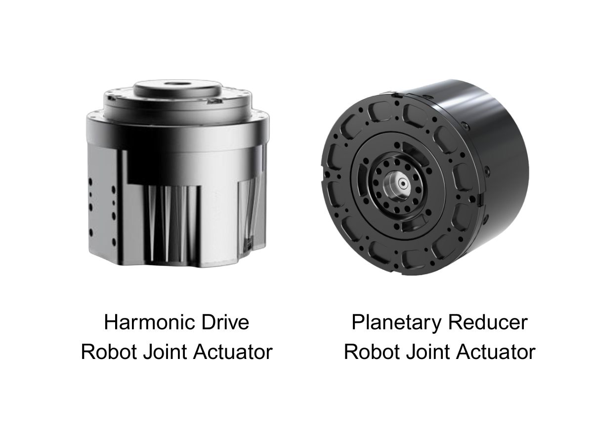
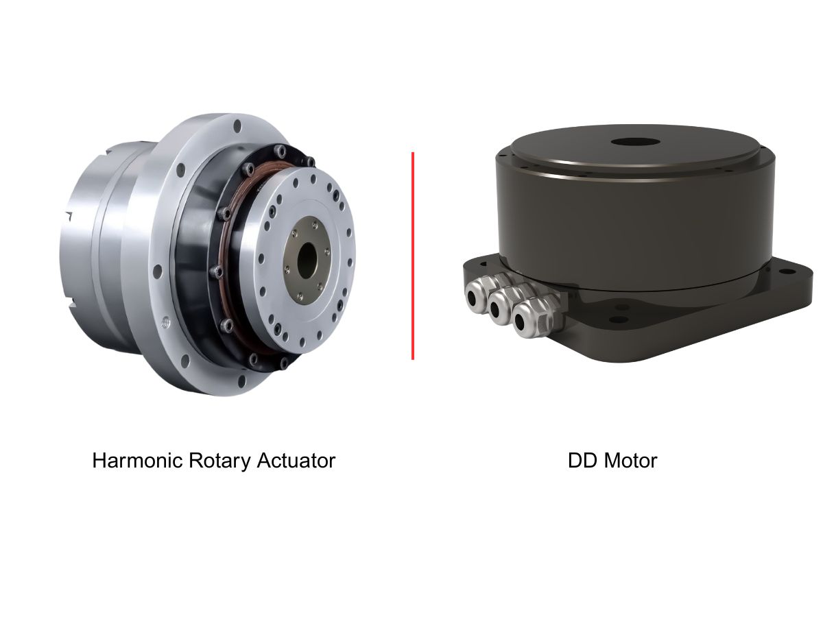
Double Click
We provide harmonic drive reducer,planetary reducer,robot joint motor,robot rotary actuators,RV gear reducer,robot end effector,dexterous robot hand
 What is robot joint actuator?How to Choose the Best Robot Rotary Joint Actuator?In core robot joint transmission solutions, planetary and harmonic rotary actuators each have their own strengths. Choosing the right type based on application requirements is essential to achieve the optimal balance between performance and cost.
 DD Motors VS Harmonic Rotary ActuatorsThis article provides an in-depth comparison between Direct Drive (DD) motors and harmonic rotary actuators, covering their transmission principles, advantages and disadvantages, and typical application fields.
 OMG Ultra Compact Harmonic Drive Joint Module with Built-in Torque SensorHONPINE TCHL series harmonic drive joint module is a game-changing product that achieves disruptive improvements in multiple aspects such as lightweight design, integration level, and connection convenience. This article will analyze its revolutionary enhancements with you.
 Why Does an RV Reducer Need Profile Modification? How to Further Reduce Backlash and Transmission Error?An RV Reducer is designed to deliver high torque, high stiffness, and precise motion for demanding applications such as robotic joints, industrial rotary tables, and precision machinery. However, achieving low backlash and stable transmission accuracy requires more than high-precision machining. Cycloidal profile modification must also account for manufacturing tolerances, assembly errors, load-induced deformation, thermal expansion, and lubrication conditions. In this article, we examine why RV reducers require profile modification, how different modification methods affect meshing, and how engineers can further control backlash and transmission error through profile design, error budgeting, structural analysis, precision manufacturing, and validation testing.
 How to Choose a Hollow Rotary Platform: A Complete Selection Guide?A hollow rotary platform is widely used in precision automation where rotary positioning, compact integration, and cable routing through the rotation axis are required. However, choosing the right platform involves more than comparing rated torque or maximum speed. Load, eccentricity, overturning moment, inertia, positioning accuracy, hollow bore, acceleration, duty cycle, and installation conditions all affect the actual performance of the rotary system. This guide explains the key parameters engineers should consider when selecting a hollow rotary platform for CNC indexing, wafer handling, vision inspection, laser processing, dispensing, and other precision rotary applications.
 Hollow Robot Joint Module: Why Cable Routing Matters in Robotic Joints?A hollow robot joint module provides an internal passage for power cables, signal lines, pneumatic tubes, and other end-effector connections. Compared with external cable routing, a hollow joint module can help reduce cable exposure, improve system integration, and create a cleaner motion path for robotic arms. This article explains why internal cable routing matters in robotic joints and what to consider when selecting a hollow joint module for robotic applications.
 Large-Bore Harmonic Joint Actuator for Humanoid Robot Waist Joints: A Practical Selection GuideThe humanoid robot waist joint is one of the most demanding motion joints in a humanoid robot. Unlike conventional robotic arm joints, it supports the upper body while handling bending, twisting, posture transitions, and continuously changing dynamic loads. At the same time, the limited internal space must accommodate power cables, signal lines, sensors, and structural components. These requirements make a large-bore harmonic joint actuator an important option for humanoid robot waist joints. This article explains how to select a suitable harmonic joint actuator by considering hollow bore size, dynamic torque, reduction ratio, mechanical rigidity, integration, and service life.
 Nabtesco RV vs Harmonic Drive vs WITTENSTEIN: Why Backlash-Free Planetary Actuators Are EmergingNabtesco RV, Harmonic Drive, and WITTENSTEIN have each established proven transmission solutions for robotics, machine tools, automation, and precision motion control. However, applications requiring both arc-second-level positioning and high mechanical rigidity can expose different trade-offs between backlash, torsional stiffness, load capacity, and transmission accuracy. This has created growing interest in a backlash-free planetary actuator that combines the rigidity and torque density of planetary transmission with advanced backlash compensation. In this article, we compare the characteristics of Nabtesco RV, Harmonic Drive, and WITTENSTEIN precision planetary gearboxes, and examine where a backlash-free planetary actuator can provide an alternative solution.
 Robot Joint Actuator Selection: From Inertia Matching to System-Level OptimizationSelecting a robot joint actuator is not simply a matter of matching motor torque or achieving a suitable inertia ratio. In a real robotic system, reduction ratio, load spectrum, thermal performance, mechanical stiffness, transmission nonlinearity, encoder architecture, control bandwidth, and service life all interact to determine the final result. A joint may meet its peak torque requirement and still experience vibration, overheating, positioning errors, or premature wear in real operation. This article examines the engineering logic behind robot joint actuator selection and explains why moving from single-parameter matching to system-level optimization can lead to more reliable and predictable robotic joint performance.
 How to Choose a Small Harmonic Actuator?HONPINE Series 11 small harmonic actuators provide a compact, high-performance rotary motion solution for precision automation applications. Available with hollow or solid shafts, 48V or 220V options, optional brakes, absolute encoders, and different reduction ratios, the Series 11 is designed for applications requiring compact dimensions, controlled torque, and precise positioning.
 How to Choose a Wheel Motor for a Heavy-Duty AGV? Key Challenges from Dynamic Loads to 120-Ton AGV Drive Wheel SystemsSelecting a Heavy-Duty AGV Wheel Motor is more than matching motor power or rated torque to the vehicle's payload. As AGVs move from conventional material handling to multi-ton and even 120-ton-class applications, the drive wheel system must handle dynamic loads, acceleration, braking, turning forces, traction, and long-term mechanical stress. The actual challenge lies in matching wheel load capacity, wheel-end torque, gearbox performance, steering architecture, suspension, and chassis design under real operating conditions. This article examines the key challenges of Heavy-Duty AGV Wheel Motor selection and explains how Steering Drive Wheels and Differential Drive Wheels can be evaluated for different heavy-duty AGV applications.
 Why Is a Planetary Gearbox an Ideal Partner for Servo Motors in CNC, AGV, Solar and Lithium Battery Equipment?A servo motor can deliver high speed, precise control and fast dynamic response, but the transmission system between the motor and the machine also determines how effectively these capabilities are transferred to the load. A planetary gearbox is widely paired with servo motors because its coaxial structure, high efficiency, low backlash, high torsional rigidity and flexible reduction ratios make it suitable for a broad range of motion systems. From CNC machine tools and industrial automation to AGVs, photovoltaic equipment and lithium battery production lines, planetary gearboxes can provide a practical balance between precision, performance and cost. This article explains why planetary gearboxes work well with servo motors and how engineers can select the right transmission for different applications.