







Harmonic vs. RV Reducers for Lithium Battery Robotic Arms: A Joint-by-Joint Selection Guide
In a lithium battery plant, reducer selection for a robotic arm is not about picking one "best" gearbox. It is about dividing the work by joint — by the torque level each joint carries, the precision it must hold, and the environment it lives in.
That is why we supply two product lines as one solution instead of forcing a choice:
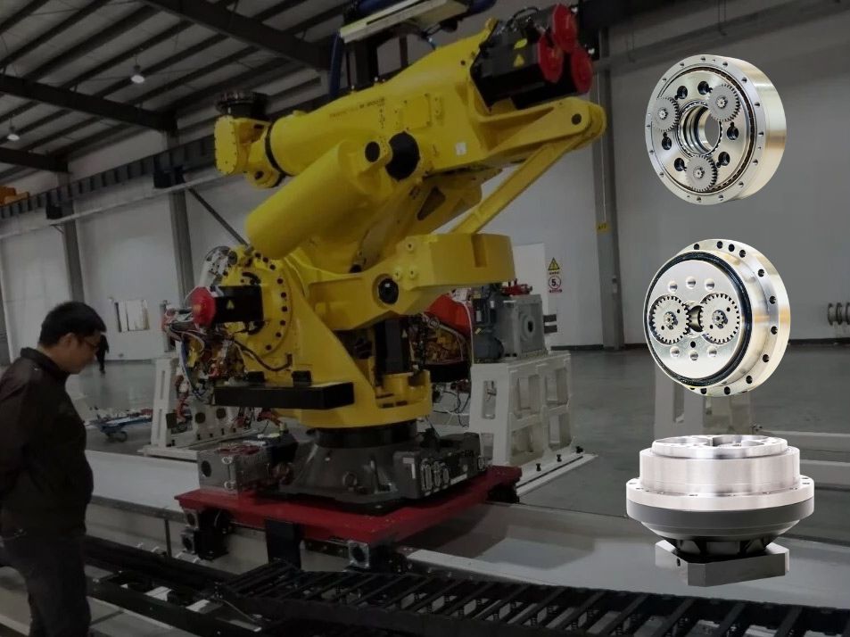
Shoulder and elbow joints (J1–J3) → RV reducers: high stiffness, shock resistance, large reduction ratios.
Wrist joints (J4–J6) → harmonic reducers: near-zero backlash, high torque density, low weight.
Cartesian coordinates and gantry transfer → planetary reducers: low cost, long travel.
On top of this general logic, lithium battery production adds two hard constraints: peak torque verification and clean lubrication (to prevent metal particles from contaminating battery cells).
What a Reducer Really Does Inside a Robot Joint?
Many selection debates go wrong because the reducer is treated as a simple "torque multiplier". Inside a joint, it actually performs four jobs at once.
The Four Jobs of a Joint Reducer
1. Speed reduction and torque multiplication — it moves the motor's operating point into its high-efficiency region, so a smaller motor delivers more torque.
2. Reverse transmission of accuracy — motor-side errors are divided by the reduction ratio N, but the reducer's own backlash and transmission error pass to the end of the arm at 100%, and are then amplified along the full arm length into end-effector position error.
3. Load carrying — the load torque is transferred from the motor shaft to the structure; the motor only produces force and controls speed.
4. Stiffness — torsional stiffness directly determines the mechanical resonance frequency, which in turn determines the servo bandwidth and the achievable cycle time.
Two Corollaries That Drive the Whole Selection
The closer a joint is to the base, the stiffer it must be. It carries the largest torques: the gravity torque of the whole arm plus the payload, and the inertial torques during acceleration.
The closer a joint is to the end effector, the lighter it must be. Every extra kilogram at the wrist forces all upstream joints and structures to be strengthened in cascade — the "weight spiral".
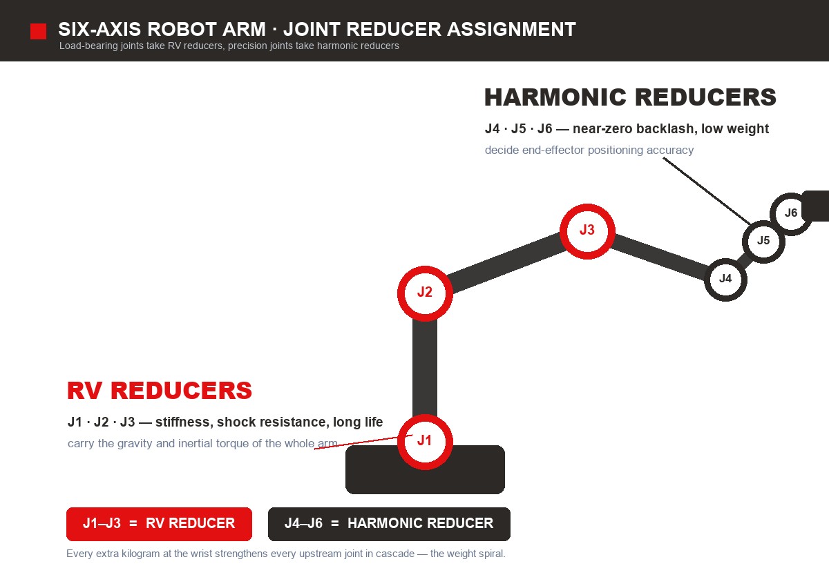
This is the engineering reason RV and harmonic reducers divide the arm spatially — and why we build the two lines as one matched solution.
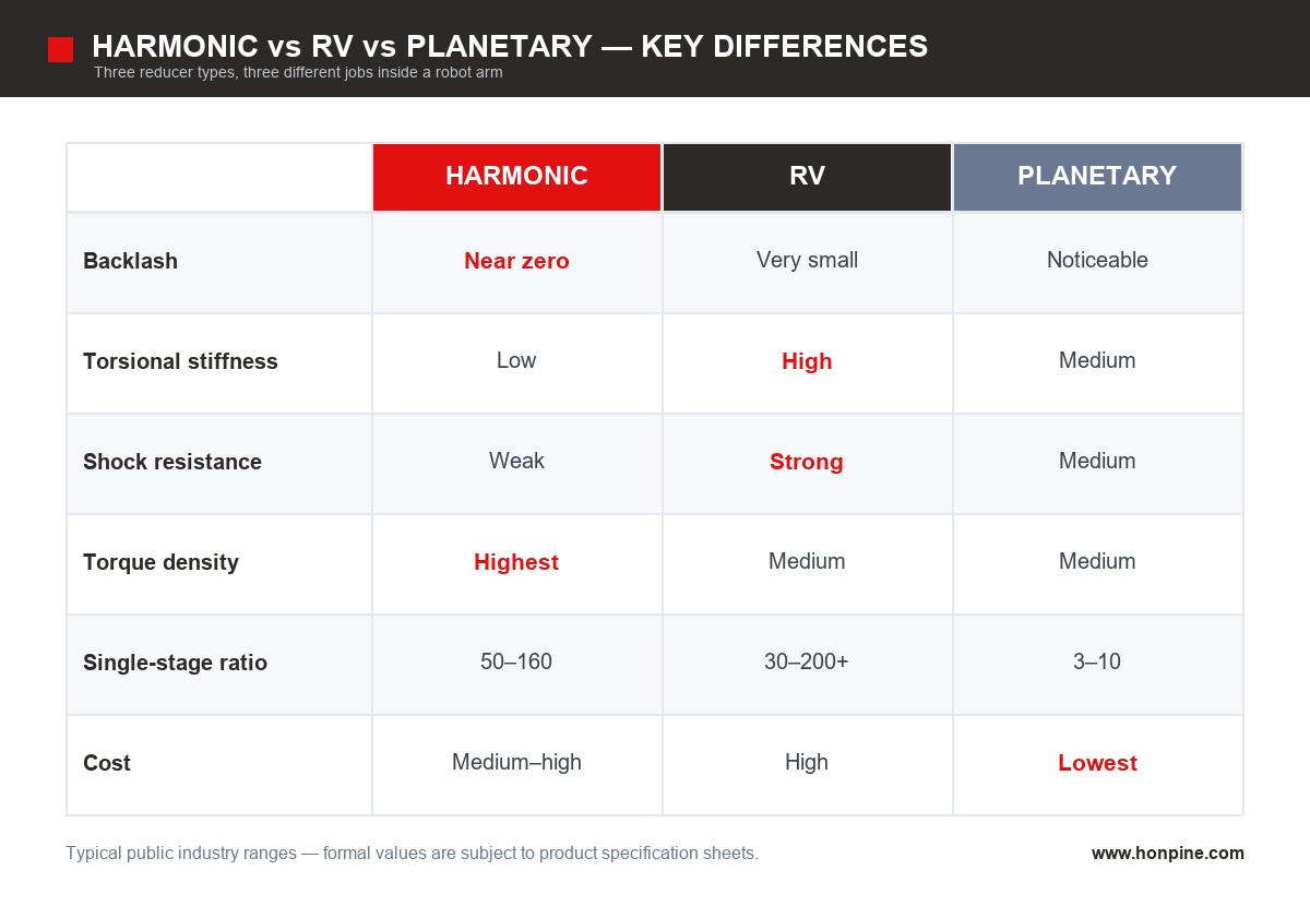
Harmonic vs. RV vs. Planetary: Where the Division of Labor Ends
One-line rule: a harmonic reducer trades stiffness for precision and light weight; an RV reducer trades size and cost for stiffness and life.
High-cycle lithium battery lines mean frequent hard acceleration and braking — large inertial torques and large emergency-stop shocks. Load-bearing joints must prioritize stiffness; only precision joints should be handed to harmonic reducers. This is not a preference, it is mechanics.
Product Line 1: Harmonic Reducers for Precision Joints (J4–J6, Light Joints, All Joints of Cobots)
Where Harmonic Reducers Fit
Wrists of six-axis robots (J4–J6)
All joints of light-payload handling robots (5–20 kg class)
All joints of collaborative robots — light weight itself is intrinsic safety, keeping collision forces controllable
High-speed pick-and-place, sorting and scanning stations on SCARA and Delta robots
Typical Parameter Ranges
Where They Do Not Fit?
Long-reach, high-inertia load-bearing joints with frequent emergency stops: the flexspline tolerates shock poorly — if peak verification fails, do not force it.
Continuous duty with very narrow grease-change windows: flexspline life must be taken seriously through L10 calculation.
Product Line 2: RV Reducers for Load-Bearing Joints (J1–J3, Positioners, Nut Runners)
Where RV Reducers Fit
Shoulders and elbows of six-axis robots (J1–J3), especially 30–200 kg heavy-payload models
Module assembly, Busbar welding, gluing: long arm reach plus high cycle rate
Flip / positioner units and nut-running stations: mainly resisting overturning moments
Any joint that needs a large ratio and must absorb emergency-stop shock
Typical Parameter Ranges
Where They Do Not Fit
Wrists and light end-effector joints: their size and weight push the burden onto every upstream joint, so the economics fail.
Long-travel linear motion: the structure is not built for long travel — a planetary reducer with rack and pinion is the better answer.
How the Two Lines Work Together on a Six-Axis Arm?
A common mistake deserves its own note: J3 should not blindly copy the conclusion for J1/J2. On light-payload models, a large-spec harmonic reducer saves real weight and cost; on heavy models, an RV is non-negotiable. The boundary must be drawn by torque calculation, not by habit.
Why Lithium Battery Production Is More Demanding Than General Automation?
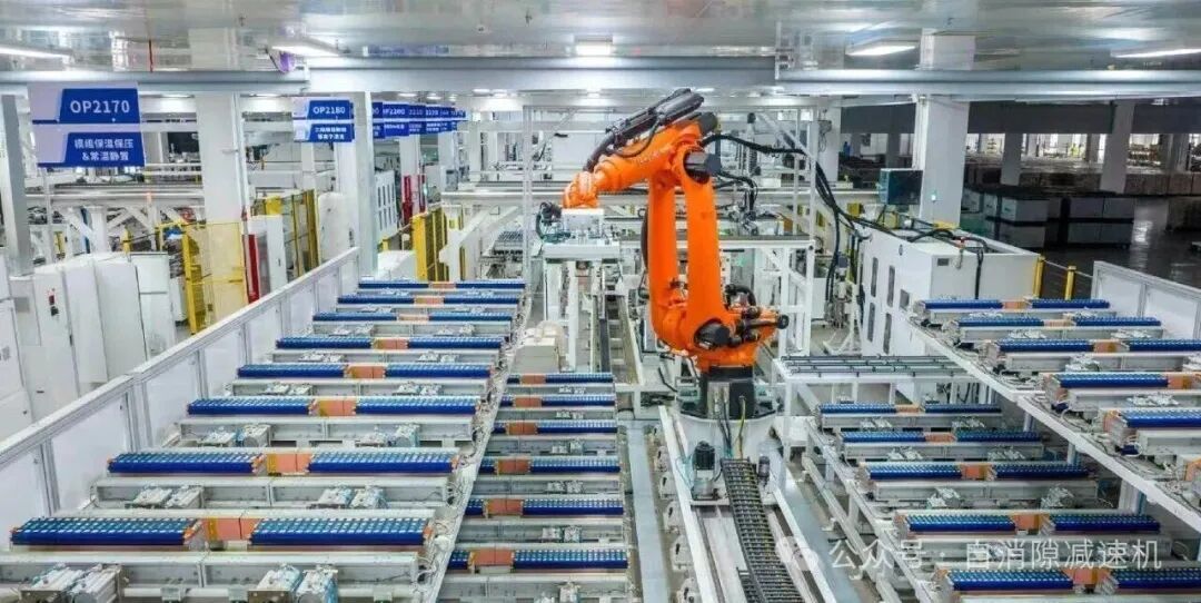
The same RV + harmonic combination that runs on an automotive welding line may fail acceptance on a lithium battery line. The difference is three extra filters.
Filter 1: Extreme Precision Requirements
Tab / cap alignment, Busbar welding, module-to-pack loading — six-axis repeatability is typically ±0.02–0.05 mm. That number is decided by "backlash + angular transmission error, multiplied by arm length". The longer the arm, the more the same backlash is amplified at the end effector. So wrist-joint backlash must be verified individually, not read from the machine's nameplate.
Filter 2: Fast Cycles and High Duty
Cell sorting and loading can reach tens to over a hundred parts per minute, with constant acceleration and deceleration. High servo bandwidth is a hard requirement — and the bandwidth ceiling equals the mechanical resonance frequency, which is set by the reducer's torsional stiffness. Insufficient stiffness shows up as the classic "stops, then shivers" residual vibration. Size by the average allowable input speed, never the instantaneous peak.
Filter 3: Zero Tolerance for Particle Contamination
Lithium batteries are extremely sensitive to metal particles — a single wear particle can cause an internal short circuit or self-discharge. Three things must be checked:
Sealing class — keep wear debris inside the joint.
Low-dust / low-vapor grease — PFPE (perfluoropolyether) types are common.
Zone-specific differences — electrolyte filling and winding areas may require dry running or special greases; filling / formation zones additionally require explosion-proof and anti-static provisions for flammable electrolyte vapor.
Stack 24/7 continuous operation on top, and reducer life plus grease intervals translate directly into downtime planning. Harmonic flexsplines must be verified by L10 life — rated torque alone is not enough.
Recommended Reducer Configuration by Station
These payload ranges are industry-typical. Real selection must be recalculated from your station's actual payload, reach, and cycle time.
A Five-Step Selection Method: From Station Data to Model Range
1. Build the joint load model. Extract each joint's static gravity torque (arm + payload), dynamic inertial torque, and emergency-stop shock torque; produce rated and peak datasets.
2. Screen the type by peak torque. High peak, long reach, frequent e-stops → RV. Moderate peak but precision-critical → harmonic. Pure long-travel linear → planetary.
3. Verify torque and overturning moment. Peak safety factor 1.5–2 as a baseline, 2–3 under impact duty; check the wrist flange's overturning moment separately, or early failure follows.
4. Check inertia, speed, and heat together. Reduction ratio, inertia ratio, average allowable input speed, and temperature rise must be solved jointly. Oversized inertia ratio brings vibration and resonance that tuning cannot fix — the symptom is a cycle time that will not go up and accuracy that will not hold.
5. Add the environmental constraints. Confirm sealing class, grease type (including low-dust / low-vapor requirements), anti-static or explosion-proof needs by production zone; add an L10 life calculation for every harmonic flexspline.
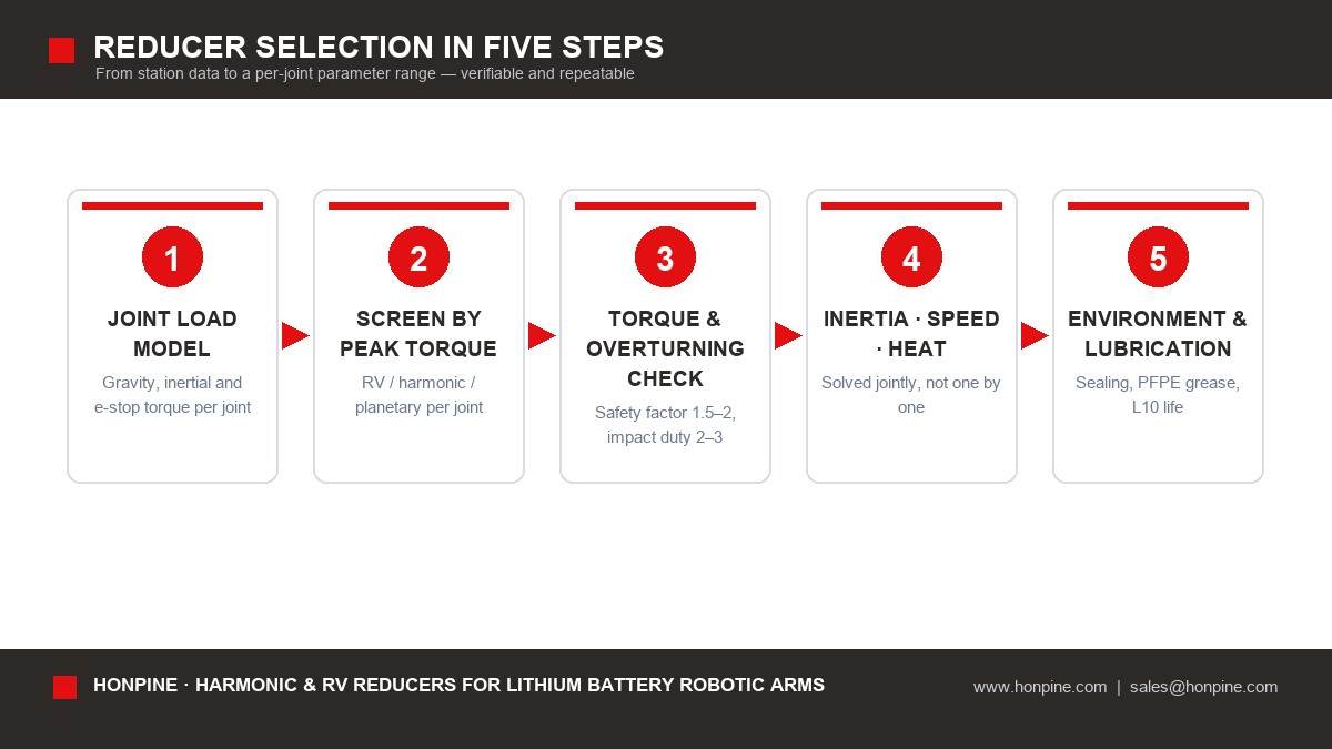
Send us the inputs of these five steps and we return parameter ranges and model ranges per joint — not a single isolated model recommendation.
Four Pitfalls That Cause Early Failures
1. Checking rated torque only, ignoring peak and overturning loads. Emergency stops on lithium battery lines push instantaneous torque to 3–5× the rated value; the wrist flange's overturning moment is often ignored completely. Use a peak safety factor of 1.5–2, and 2–3 under impact duty.
2. Ignoring heat and duty cycle. Frequent acceleration heats the reducer, aging the grease and drifting the accuracy. Size by average allowable input speed, not instantaneous value.
3. Ignoring grease–cleanroom compatibility. Vapor and dust generation contaminate cells; filling / formation zones add explosion-proof and anti-static requirements. This is the core difference from general automotive lines — and where copied configuration sheets fail.
4. Mismatched inertia between reducer and motor. An oversized inertia ratio brings vibration and resonance that are hard to tune; the result is a cycle time that will not rise and accuracy that will not hold. Inertia matching must be solved jointly with ratio, precision, and stiffness.
Engineer FAQ
How should backlash actually be compared?
Confirm the definition and measuring conditions first (loading method, measuring position, whether hysteresis is included), then compare numbers. Backlash values measured under different definitions cannot be compared directly — which is why some reducers with "better numbers" perform worse on the floor.
Should J3 use an RV or a harmonic reducer?
Let the torque calculation draw the boundary. On light-payload models a large-spec harmonic saves weight and cost; on heavy, long-reach models the RV is mandatory. Not by habit.
How do we specify grease for cleanroom duty?
Low-dust / low-vapor PFPE grease is the common choice; winding and filling areas may require dry running or special greases. Confirm grade and cleanliness class by zone. [To be confirmed: HONPINE lubrication options and compatibility notes]
How do we size harmonic flexspline life honestly?
Never from rated torque alone: calculate L10 life, state the recommended grease-change interval, and write that window into the downtime plan.
How do we plan maintenance for 24/7 operation?
Map life and grease intervals directly into the downtime plan, then back-calculate the acceptable maintenance frequency from your OEE target. The higher the OEE goal, the more reducer life equals capacity.
Can you just recommend a specific model?
We prefer to start with parameter ranges: give us payload, reach, cycle time, accuracy, and zone, and we return torque ranges and type assignments per joint first, then converge to model ranges. The logic stays reusable when you change suppliers or redesign. [To be confirmed: HONPINE model naming and specification tables]
Next Step: Send Us One Workstation
If you have a specific station in hand, provide these six inputs and we will calculate the reducer parameter range for every joint using the five-step method above:
1. Payload mass (including end-of-arm tooling)
2. Reach / arm length distribution
3. Cycle time and motion profile (including maximum acceleration)
4. Target repeatability
5. Production zone (dry room / cleanroom / electrolyte filling / formation / assembly …)
6. Mounting interface and space limits
[To be confirmed: inquiry form fields, sample request entry, service and spare-part policy, technical support response time]
Parameter and Compliance Notes
All parameter ranges in this article are public, industry-typical values used to explain selection logic; they are not performance commitments. Formal parameters are subject to HONPINE product specification sheets.
Read More
Learn more about the story of HONPINE and industry trends related to precision transmission.
 What is robot joint actuator?How to Choose the Best Robot Rotary Joint Actuator?In core robot joint transmission solutions, planetary and harmonic rotary actuators each have their own strengths. Choosing the right type based on application requirements is essential to achieve the optimal balance between performance and cost.
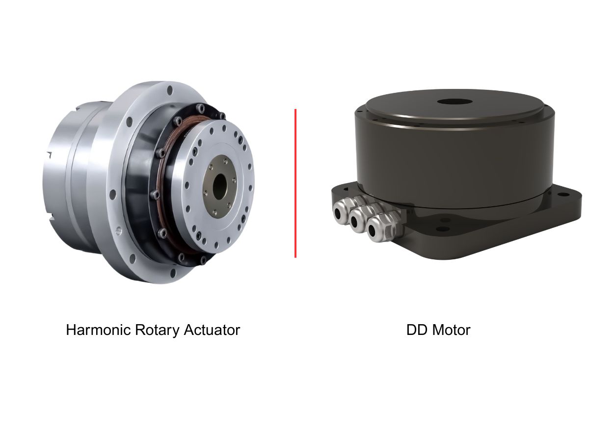
 DD Motors VS Harmonic Rotary ActuatorsThis article provides an in-depth comparison between Direct Drive (DD) motors and harmonic rotary actuators, covering their transmission principles, advantages and disadvantages, and typical application fields.
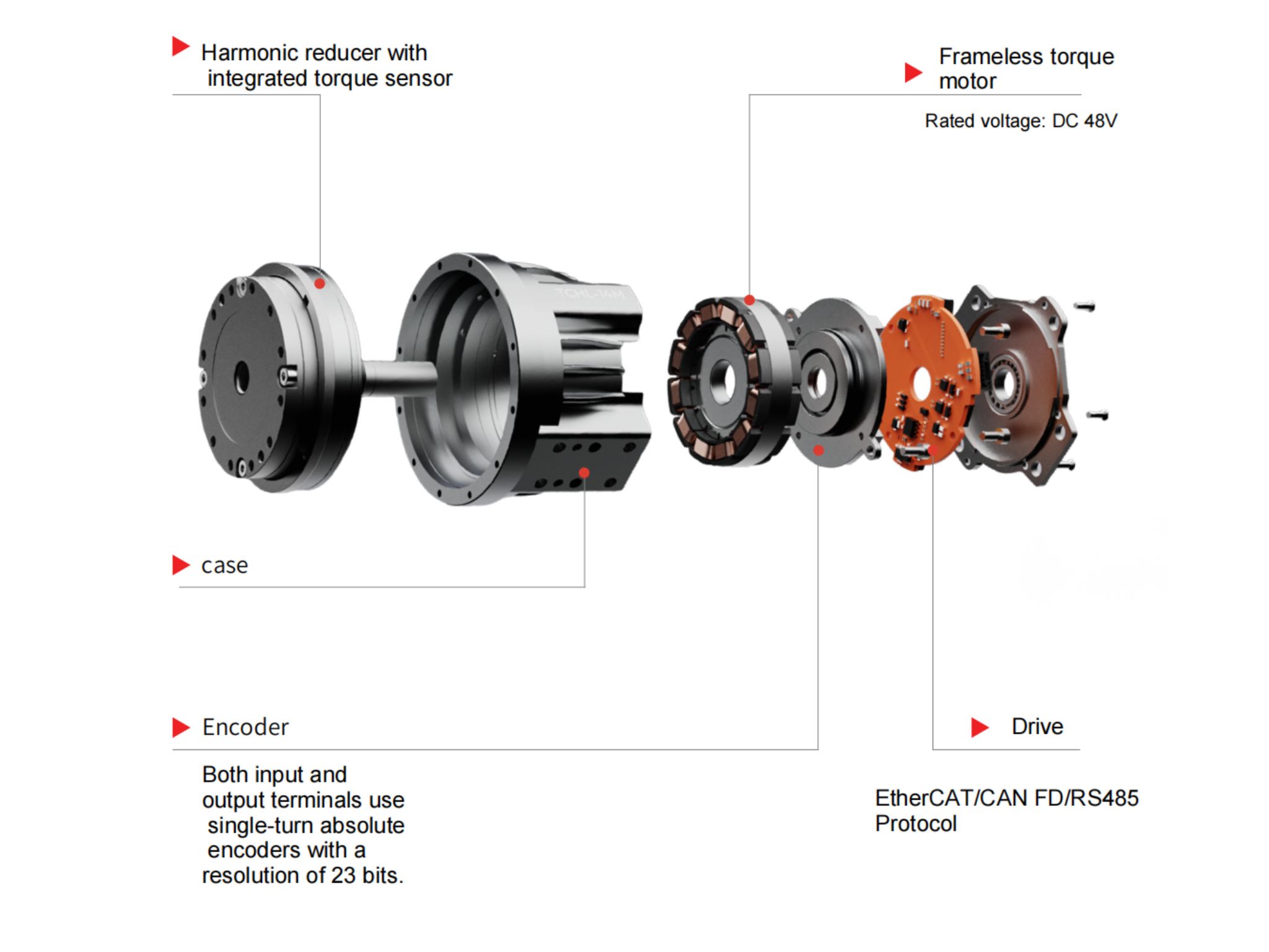
 OMG Ultra Compact Harmonic Drive Joint Module with Built-in Torque SensorHONPINE TCHL series harmonic drive joint module is a game-changing product that achieves disruptive improvements in multiple aspects such as lightweight design, integration level, and connection convenience. This article will analyze its revolutionary enhancements with you.
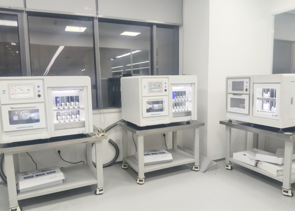
 The Role of Harmonic Drive Gears in Achieving 5–10 μm Accuracy in Dental Milling MachinesA dental milling machine is a CNC machining system used to directly process digital dental models into restorations such as crowns, bridges, veneers, inlays, and implant abutments. Dental milling machines require far higher operational accuracy and motion stability than ordinary equipment. This article explains how harmonic drive gear help dental milling machines achieve stable, continuous, and controllable operation.
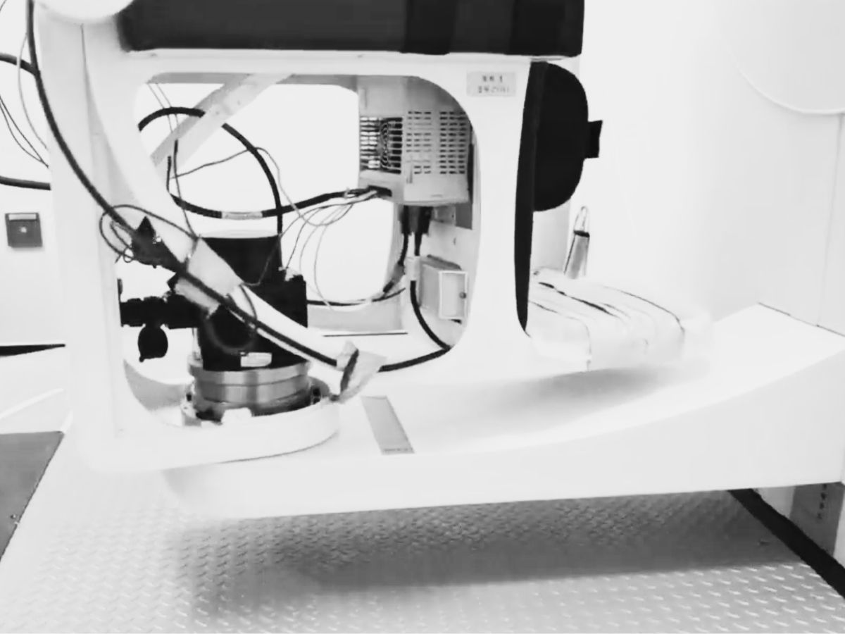
 Why Are Harmonic Rotary Actuators Perfect for Medical Equipment?Harmonic rotary actuators (typically integrated systems consisting of a harmonic drive reducer, frameless torque motor, encoder, and optional brake) are regarded as key components in medical equipment. The core reason is that they simultaneously meet the most stringent medical requirements for precision, compact size, safety, and controllability. The following explanation is structured from three perspectives: technical characteristics, application scenarios, and medical value.
 High-Precision RV Reducers Perfectly Matched for Walking RobotsThe walking axis of a robot is a core component for power transmission and support. RV reducers provide extremely high rigidity, precision, and torque while maintaining a compact size and exceptional reliability, making them an ideal match for the demanding requirements of walking robot joints in terms of load capacity, impact resistance, and precision.
 Harmonic vs. RV Reducers for Lithium Battery Robotic Arms: A Joint-by-Joint Selection GuideIn lithium battery plants, reducer selection for a robotic arm is not about finding one "best" gearbox — it is about dividing work by joint. RV reducers take the shoulder and elbow (J1–J3), where stiffness, shock resistance, and long life matter most; harmonic reducers take the wrist (J4–J6), where near-zero backlash, high torque density, and low weight decide positioning accuracy. Planetary gearboxes cover long-travel Cartesian transfer at lower cost. Lithium battery production then adds three stricter filters: extreme repeatability (±0.02–0.05 mm), 24/7 high-duty cycles, and zero tolerance for metal particle contamination. This guide explains the logic behind joint-by-joint selection, compares the three reducer types, and maps typical configurations for every station.
 How to Choose High-Precision Rotary Actuators for Industrial Automation?High-precision rotary actuators play an important role in industrial automation, where positioning accuracy, repeatability, durability and installation flexibility directly affect equipment performance. HONPINE offers four main series of precision rotary actuators, including HAT, HAM and HAS harmonic rotary actuators and HPG low-backlash planetary actuators. With torque ratings ranging from 4 to 1,494 Nm across the product range, these solutions are designed for applications in semiconductor manufacturing, 3C automation, laser processing and CNC machine tools. Learn how to identify the right rotary actuator based on operating conditions, precision requirements and mechanical integration needs.
 Why Are Harmonic Reducers Suitable for High-Precision Automation Equipment?Precision automation equipment depends on consistent rotary motion, reliable positioning and compact transmission design. From dispensing head orientation and component angular alignment to automated inspection indexing, harmonic reducers offer a practical solution for applications requiring low backlash and high reduction ratios in limited installation space. This article explains how harmonic reducers support repeatable motion, compares key design configurations, and outlines how to select a suitable reduction ratio and reducer structure based on load, speed, accuracy and machine cycle-time requirements.
 Why Are Servo Motors and Gear Reducers an Ideal Match?Servo motors provide fast, precise motion control, while gear reducers adapt their speed and torque to the load. This guide explains how servo motors and gear reducers work together through torque multiplication, reflected inertia reduction and finer theoretical position resolution. Learn how inertia matching, backlash, torsional stiffness and reduction ratio influence performance in robotics and industrial automation.
 How to Select and Use Robotic Joint Modules?How do you take robotic joint modules from selection to controlled motion? Using the HONPINE HPJM harmonic joint module as an example, Technical Director Theodore Li explains the key steps in mechanical installation, electrical wiring, CAN and EtherCAT configuration, and control commissioning. Learn what to confirm before integration and how to approach setup so each joint can respond correctly to your controller.
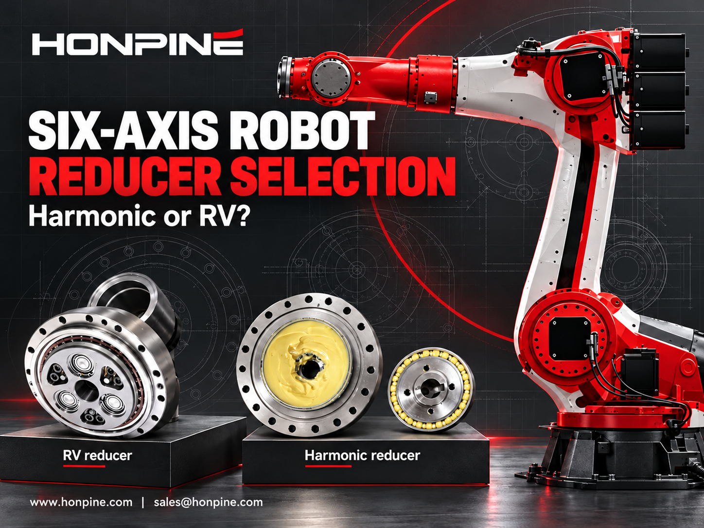
 How to Select Harmonic and RV Reducers for Each Axis of a Six-Axis Robot?What determines whether a six-axis robot joint needs a harmonic reducer or an RV reducer? The answer depends on torque, inertia, impact loads, bearing loads and installation space. This guide explains how to evaluate harmonic and RV reducers for the base, shoulder, elbow and wrist, with practical checks for stiffness, backlash and service life. Use the requirements of each axis to select a suitable reducer configuration.
Double Click
We provide harmonic drive reducer,planetary reducer,robot joint motor,robot rotary actuators,RV gear reducer,robot end effector,dexterous robot hand
 What is robot joint actuator?How to Choose the Best Robot Rotary Joint Actuator?In core robot joint transmission solutions, planetary and harmonic rotary actuators each have their own strengths. Choosing the right type based on application requirements is essential to achieve the optimal balance between performance and cost.
 DD Motors VS Harmonic Rotary ActuatorsThis article provides an in-depth comparison between Direct Drive (DD) motors and harmonic rotary actuators, covering their transmission principles, advantages and disadvantages, and typical application fields.
 OMG Ultra Compact Harmonic Drive Joint Module with Built-in Torque SensorHONPINE TCHL series harmonic drive joint module is a game-changing product that achieves disruptive improvements in multiple aspects such as lightweight design, integration level, and connection convenience. This article will analyze its revolutionary enhancements with you.
 Harmonic vs. RV Reducers for Lithium Battery Robotic Arms: A Joint-by-Joint Selection GuideIn lithium battery plants, reducer selection for a robotic arm is not about finding one "best" gearbox — it is about dividing work by joint. RV reducers take the shoulder and elbow (J1–J3), where stiffness, shock resistance, and long life matter most; harmonic reducers take the wrist (J4–J6), where near-zero backlash, high torque density, and low weight decide positioning accuracy. Planetary gearboxes cover long-travel Cartesian transfer at lower cost. Lithium battery production then adds three stricter filters: extreme repeatability (±0.02–0.05 mm), 24/7 high-duty cycles, and zero tolerance for metal particle contamination. This guide explains the logic behind joint-by-joint selection, compares the three reducer types, and maps typical configurations for every station.
 How to Choose High-Precision Rotary Actuators for Industrial Automation?High-precision rotary actuators play an important role in industrial automation, where positioning accuracy, repeatability, durability and installation flexibility directly affect equipment performance. HONPINE offers four main series of precision rotary actuators, including HAT, HAM and HAS harmonic rotary actuators and HPG low-backlash planetary actuators. With torque ratings ranging from 4 to 1,494 Nm across the product range, these solutions are designed for applications in semiconductor manufacturing, 3C automation, laser processing and CNC machine tools. Learn how to identify the right rotary actuator based on operating conditions, precision requirements and mechanical integration needs.
 Why Are Harmonic Reducers Suitable for High-Precision Automation Equipment?Precision automation equipment depends on consistent rotary motion, reliable positioning and compact transmission design. From dispensing head orientation and component angular alignment to automated inspection indexing, harmonic reducers offer a practical solution for applications requiring low backlash and high reduction ratios in limited installation space. This article explains how harmonic reducers support repeatable motion, compares key design configurations, and outlines how to select a suitable reduction ratio and reducer structure based on load, speed, accuracy and machine cycle-time requirements.
 Why Are Servo Motors and Gear Reducers an Ideal Match?Servo motors provide fast, precise motion control, while gear reducers adapt their speed and torque to the load. This guide explains how servo motors and gear reducers work together through torque multiplication, reflected inertia reduction and finer theoretical position resolution. Learn how inertia matching, backlash, torsional stiffness and reduction ratio influence performance in robotics and industrial automation.
 How to Select and Use Robotic Joint Modules?How do you take robotic joint modules from selection to controlled motion? Using the HONPINE HPJM harmonic joint module as an example, Technical Director Theodore Li explains the key steps in mechanical installation, electrical wiring, CAN and EtherCAT configuration, and control commissioning. Learn what to confirm before integration and how to approach setup so each joint can respond correctly to your controller.
 How to Select Harmonic and RV Reducers for Each Axis of a Six-Axis Robot?What determines whether a six-axis robot joint needs a harmonic reducer or an RV reducer? The answer depends on torque, inertia, impact loads, bearing loads and installation space. This guide explains how to evaluate harmonic and RV reducers for the base, shoulder, elbow and wrist, with practical checks for stiffness, backlash and service life. Use the requirements of each axis to select a suitable reducer configuration.
 Top 7 RV Reducer Gearbox Manufacturers: Why Does Nabtesco Still Dominate?What sets RV reducer gearbox manufacturers apart, and why does Nabtesco remain a benchmark in this market? RV reducer production demands precise component machining, careful assembly and extensive engineering know-how. This article introduces seven manufacturers across RV reducers and related transmission technologies, examines the strengths behind Nabtesco's position, and explores HONPINE's development capabilities to help you understand the supplier landscape.
 How to Calculate Torque for a Harmonic Rotary Actuator in a Flipping Mechanism?How much torque does a harmonic rotary actuator need to flip a 10 kg load through 180 degrees? The answer depends on more than weight. Center-of-gravity offset, load inertia, acceleration and operating frequency all affect actuator selection. In this guide, Theodore Li, Technical Director at HONPINE, explains the calculation process using a horizontal-axis flipping example and outlines the checks needed for peak torque, continuous operation, output speed and bearing loads.
 Why Are Harmonic Reducers Suitable for CNC Machine Tool Rotary Tables?Why choose harmonic reducers for CNC rotary tables? Accurate indexing depends on more than the motor: backlash, torsional stiffness and torque capacity all affect how reliably a rotary table holds its position during machining. This guide explains the key transmission requirements of fourth and fifth axis rotary tables, explores common machine tool applications, and introduces HONPINE harmonic reducer configurations for different installation and load requirements.