








How to Calculate Torque for a Harmonic Rotary Actuator in a Flipping Mechanism?
Hello everyone, I'm Theodore Li, Technical Director at HONPINE.
When selecting harmonic rotary actuators for 3C automation equipment, many customers ask us a common question:
"My flipping mechanism needs to rotate a 10 kg load by 180 degrees. How much torque does the harmonic rotary actuator need?"
This is a typical challenge in precision automation equipment design.
In smartphone frame flipping machines, PCB flipping systems, electronic component assembly equipment, and automated vision inspection machines, flipping mechanisms must achieve accurate and stable rotational motion within limited installation space.
However, knowing only the load weight and flipping angle is not enough to determine the required actuator torque.
Engineers must also consider the distance between the center of gravity and the rotation axis, load inertia, flipping speed, acceleration and deceleration time, and operating frequency.
In this article, I will explain how to calculate the required output torque for a harmonic rotary actuator, using a practical example from a 3C automation flipping mechanism.
Why Is Torque Calculation Important for Flipping Mechanisms in 3C Automation?
In electronics manufacturing, many automated machines use flipping mechanisms to change the orientation of workpieces between production processes.
Typical applications include smartphone frame flipping, PCB handling, camera module assembly, and multi-angle visual inspection.
These applications have different motion requirements.
For example, a smartphone frame flipping machine may need to complete a 180° rotation within a short cycle time, while a precision vision inspection machine may place greater emphasis on stability and repeatability after positioning.
If the actuator cannot provide sufficient torque, the mechanism may fail to achieve the required acceleration, trigger overload alarms, or become unable to complete the flipping motion.
Conversely, selecting an excessively large actuator can increase equipment cost, weight, and installation space without necessarily improving positioning performance.
Therefore, accurate torque calculation is an essential step when selecting harmonic rotary actuators for automated flipping mechanisms.
What Parameters Are Needed to Calculate Flipping Mechanism Torque?
Before calculating the required torque, engineers should confirm the rotating mass, center-of-gravity position, load inertia, rotation angle, motion time, and operating conditions.
Two important factors are frequently overlooked.
The Workpiece Weight Is Not the Total Rotating Load
Suppose a smartphone frame weighs only 0.5 kg, while the fixture holding it weighs 4 kg.
The torque calculation must account for the entire rotating assembly rather than the smartphone frame alone.
Additional rotating components, such as mounting plates and adapters, should also be considered where applicable.
The Center-of-Gravity Position Is Critical
Two loads of identical mass can require very different gravitational torques.
If the center of gravity lies directly on the rotation axis, the static gravitational torque about that axis is zero.
However, if the center of gravity is offset by 100 mm, gravity can generate a considerable torque during rotation.
Therefore, the mechanical arrangement and center-of-gravity position must be determined before calculating the required actuator torque.
What Are the Main Components of Flipping Mechanism Torque?
For a flipping mechanism rotating around a horizontal axis, the required actuator output torque generally includes three major components:
Gravity torque
Acceleration torque
Friction and other resistance torque
Using a consistent positive rotation direction, the basic equation of motion is:
T_out(t) = J_total × α(t) + T_g(t) + T_f(t) + T_ext(t)
Where:
T_out: Instantaneous required output torque (N·m)
J_total: Total moment of inertia referred to the output axis (kg·m²)
α: Angular acceleration (rad/s²)
T_g: Torque required to counteract gravity (N·m)
T_f: Friction resistance torque (N·m)
T_ext: Additional torque caused by external process forces (N·m)
These torque components have directions.
During operation, gravity may resist rotation in one part of the movement and assist rotation in another.
Therefore, it is not always correct to assume that all torque components act in the same direction.
For preliminary sizing, engineers can use a conservative estimate:
T_estimate = |T_g|max + |T_a|max + |T_f|max + |T_ext|max
This equation is useful for initially screening actuator models.
However, final sizing should be based on the actual motion profile and instantaneous torque requirements throughout the operating cycle.
Step 1: How to Calculate Gravity Torque in a Flipping Mechanism
Gravity torque is one of the most important factors when designing a horizontal-axis flipping mechanism.
If the load's center of gravity does not coincide with the rotation axis, gravity creates a moment around that axis.
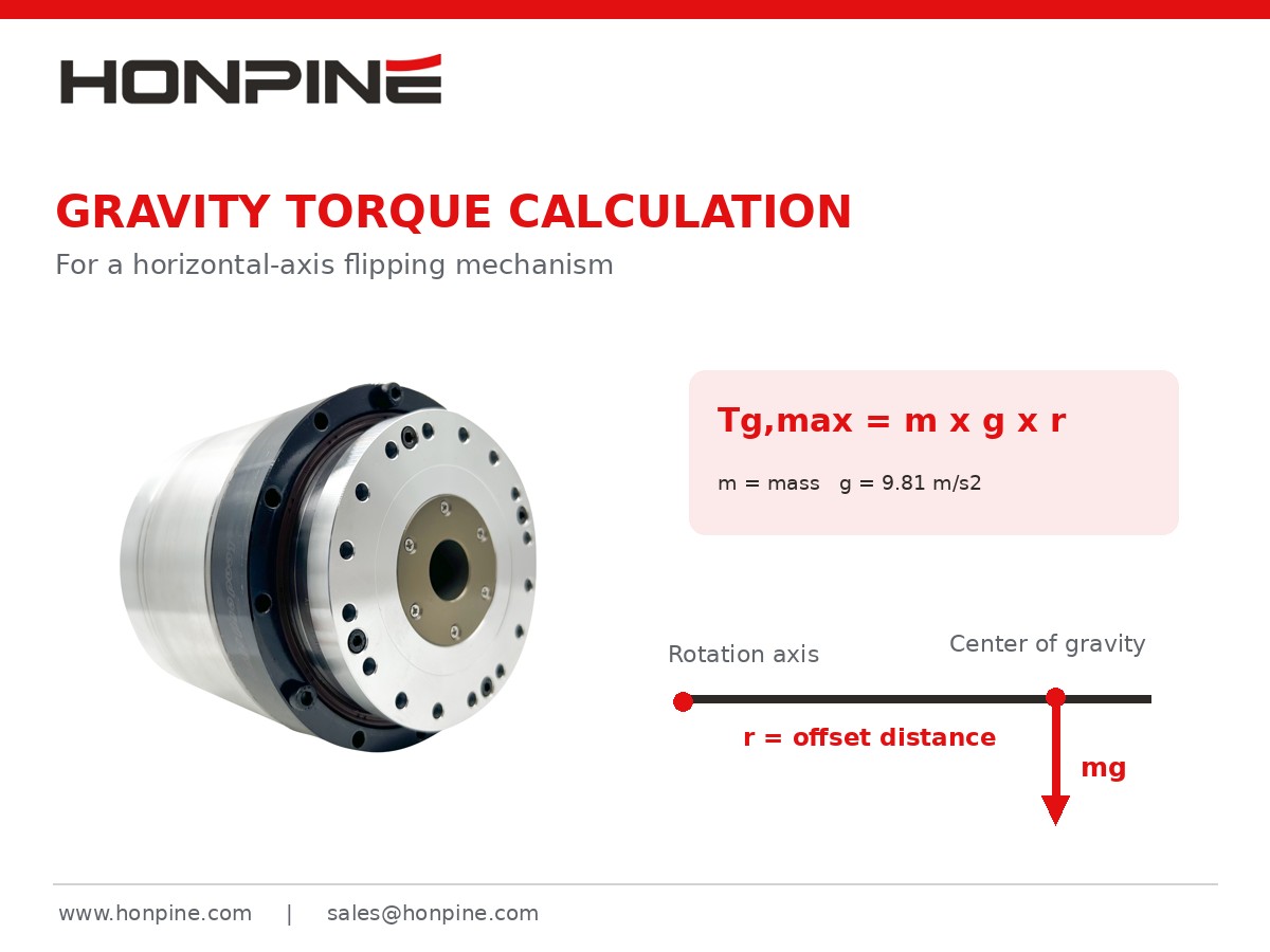
The maximum gravity torque can be calculated as follows:
T_g,max = m × g × r
Where:
m: Total mass of the rotating assembly (kg)
g: Gravitational acceleration, approximately 9.81 m/s²
r: Distance between the center of gravity and the rotation axis (m)
The distance r refers to the center-of-gravity offset, not the actuator output shaft radius.
Example: A 10 kg Load with a 100 mm Center-of-Gravity Offset
Suppose a smartphone frame flipping machine has a combined workpiece and fixture mass of 10 kg.
The center of gravity is located 100 mm from the horizontal rotation axis.
Given:
Total mass = 10 kg
Center-of-gravity offset = 0.1 m
Gravitational acceleration = 9.81 m/s²
Substitute these values into the equation:
T_g,max = 10 × 9.81 × 0.1
T_g,max = 9.81 N·m
Therefore, when the line connecting the center of gravity and rotation axis is horizontal, the maximum gravity torque is approximately 9.81 N·m.
However, when the center of gravity lies directly above or below the rotation axis, the static gravity torque becomes zero.
This demonstrates that gravity torque changes with the rotational position rather than remaining constant throughout the flipping process.
For a vertical-axis rotary mechanism, gravity generally does not create direct static torque around the rotation axis, provided there are no additional gravity-induced loading effects.
Step 2: How to Calculate the Load Moment of Inertia
Gravity torque alone is not sufficient for selecting an actuator.
In automated equipment, flipping mechanisms frequently accelerate, rotate, and decelerate within a short period.
Therefore, the moment of inertia must also be considered.
The moment of inertia describes an object's resistance to changes in angular velocity.
For a load that can be approximated as a concentrated mass:
J = m × r²
However, this equation is only suitable for a point-mass approximation or for calculating the inertia contribution caused by the offset of the center of gravity.
For real workpieces with measurable dimensions, the object's own moment of inertia must also be included.
According to the parallel-axis theorem:
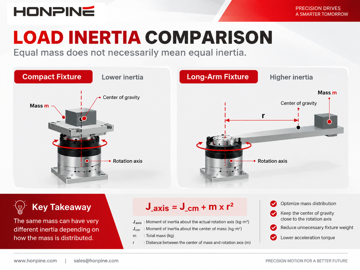
J_axis = J_cm + m × r²
Where:
J_axis: Moment of inertia about the actual rotation axis
J_cm: Moment of inertia about a parallel axis passing through the center of mass
m: Load mass
r: Distance between the center of mass and the rotation axis
Why Is Load Weight Alone Not Enough to Determine Inertia?
Consider two fixtures with the same total mass.
The first fixture has a compact structure, with most of its mass concentrated near the rotation axis.
The second fixture has an extended structure, with a larger proportion of its mass positioned farther from the rotation axis.
Although both fixtures have the same mass, the second may have a significantly higher moment of inertia.
Consequently, it requires greater acceleration torque to achieve the same angular acceleration.
For complex smartphone frame fixtures, PCB holding frames, and dual-sided flipping mechanisms, engineers should preferably use CAD software such as SolidWorks or Inventor to determine the actual moment of inertia about the designed rotation axis.
Step 3: How to Calculate Acceleration Torque
The acceleration torque required by a flipping mechanism depends mainly on the total moment of inertia and the required angular acceleration.
The formula is:
T_a = J_total × α
If the target angular velocity and acceleration time are known, assuming constant angular acceleration:
α = ω_max / t_a
Where:
ω_max: Maximum angular velocity (rad/s)
t_a: Acceleration time (s)
Does a 180° Flipping Mechanism Always Require More Torque?
Not necessarily.
The flipping angle alone does not determine the maximum required torque.
Consider two machines that both rotate a workpiece through 180°:
Machine A completes the motion in 3 seconds.
Machine B completes the motion in 0.6 seconds.
If both machines have identical loads and use the same type of motion profile, Machine B will generally require greater angular acceleration and, consequently, greater acceleration torque.
However, the final result also depends on the acceleration and deceleration phases, the motion profile, and the orientation of the load.
For short movements, a triangular velocity profile may be used without a constant-speed phase.
Therefore, dividing the flipping angle by the total movement time does not directly provide the angular acceleration.
Step 4: How to Account for Friction Torque and Safety Factors
In addition to gravity and acceleration torque, engineers must consider resistance caused by bearings, seals, and other mechanical components.
During preliminary design, friction torque may be estimated from bearing specifications, measurements from similar machinery, or conservative engineering assumptions.
However, it is not advisable to apply a fixed friction percentage to every mechanism without considering its actual construction.
What Safety Factor Should Be Used?
Engineering designs often include a torque margin to account for uncertainty in load conditions.
For example, a preliminary calculation may apply a factor of 1.5:
T_design = 1.5 × T_estimate
The factor of 1.5 is used here only as an illustrative assumption. It is not a universal selection requirement for HONPINE actuators.
Applications involving frequent starts and stops, shock loads, or substantial changes in payload may require different margins.
The selected actuator must also satisfy the manufacturer's rated torque, repeated peak torque, and instantaneous peak torque limits.
Importantly, a safety factor cannot replace continuous torque and thermal calculations.
An actuator that successfully completes one flipping cycle may still overheat when operated repeatedly at a high duty cycle.
Practical Example: How to Select a Harmonic Rotary Actuator for a Smartphone Frame Flipping Machine
Let's examine a complete calculation example based on a 3C automation application.
Suppose an automation equipment manufacturer is developing a smartphone frame flipping machine.
The machine uses a fixture to hold the workpiece and a harmonic rotary actuator to rotate the assembly through 180° around a horizontal axis.
1. Define the Operating Parameters
Assume that the rotating mass and moment of inertia have been determined using CAD software.
These values are hypothetical and are intended to demonstrate the calculation method. They are not measured specifications of a particular HONPINE actuator or an actual customer project.
2. Calculate Maximum Gravity Torque
Using the formula:
T_g,max = m × g × r
Substitute:
T_g,max = 10 × 9.81 × 0.1
T_g,max = 9.81 N·m
3. Calculate Angular Acceleration
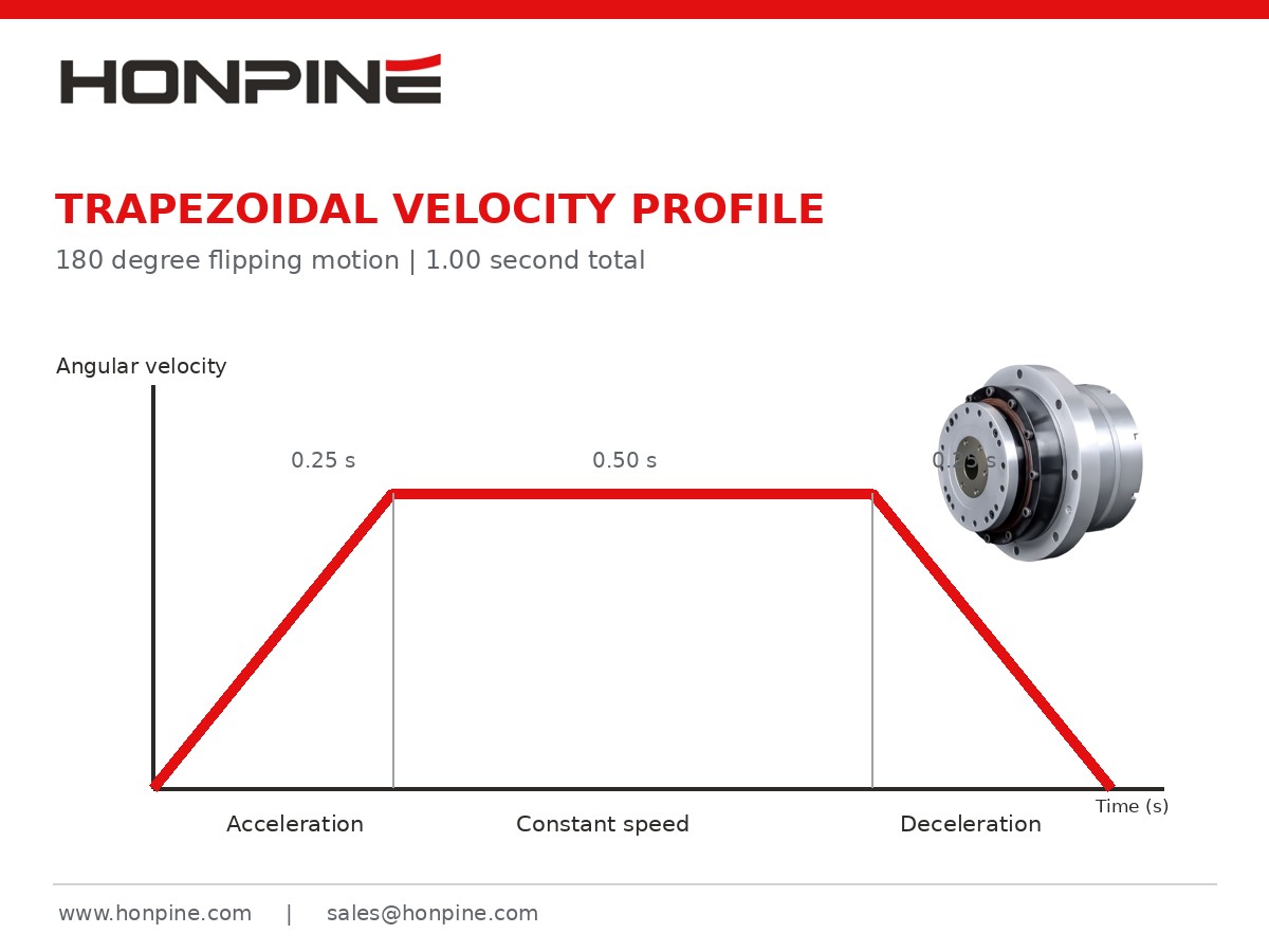
In this example, the mechanism uses a symmetrical trapezoidal velocity profile:
Acceleration: 0.25 seconds
Constant speed: 0.50 seconds
Deceleration: 0.25 seconds
First, convert the flipping angle into radians:
180° = π rad
For a symmetrical trapezoidal velocity profile:
ω_max = θ / (t − t_a)
Substitute:
ω_max = π / (1.0 − 0.25)
ω_max ≈ 4.189 rad/s
Then calculate angular acceleration:
α = 4.189 / 0.25
α ≈ 16.76 rad/s²
4. Calculate Acceleration Torque
Given:
J = 0.12 kg·m²
α = 16.76 rad/s²
Using:
T_a = J × α
T_a = 0.12 × 16.76
T_a ≈ 2.01 N·m
This represents the acceleration torque associated with the assumed load inertia.
Additional inertia from internal actuator components has not yet been included.
5. Estimate Required Peak Output Torque
For preliminary actuator selection, we conservatively add the maximum gravity torque, acceleration torque, and assumed friction torque.
T_estimate = 9.81 + 2.01 + 0.5
T_estimate = 12.32 N·m
Next, apply the illustrative design margin:
T_design = 12.32 × 1.5
T_design = 18.48 N·m
The calculation results are summarized below.
Under these assumed conditions, approximately 18.5 N·m can be used as an initial peak output torque screening target.
However, this does not mean that choosing an actuator with a rated torque above 18.5 N·m automatically guarantees suitability.
The calculation uses conservative torque addition and does not fully account for internal rotating inertia, the direction of individual torque components at each angle, or thermal loading during repeated operation.
Final selection requires checking repeated peak torque, continuous rated torque, operating speed, and the actual duty cycle.
Why Is Peak Torque Alone Not Enough for Harmonic Rotary Actuator Selection?
In real 3C automation equipment, a single flipping movement represents only part of the overall operating cycle.
For example, a smartphone frame flipping machine may perform 20 or more flipping operations per minute.
The actuator may repeatedly accelerate, rotate, decelerate, and hold its position.
Even when the peak torque requirement is satisfied, frequent operation can produce considerable thermal loading.
Therefore, engineers should also evaluate the root mean square torque, commonly called RMS torque.
T_RMS = √[(Σ T_i² × t_i) / (Σ t_i)]
Where:
T_i: Torque during each operating stage
t_i: Duration of each stage
n: Number of stages in a complete operating cycle
The calculation should include the complete forward-and-return cycle, including holding periods.
For actuators without a mechanical brake, maintaining a stationary position against gravity may require continuous motor torque and produce additional heat.
Motor-side RMS torque is not necessarily equal to output-side RMS torque. Conversion requires consideration of the transmission ratio, efficiency, internal losses, and actuator specifications.
Therefore, peak torque and continuous thermal performance must be checked separately.
What Other Parameters Should Be Checked Besides Torque?
1. Output Bearing Load Capacity
In many flipping mechanisms, the workpiece and fixture generate more than just driving torque.
They may also apply radial loads, axial loads, or overturning moments to the actuator's output bearing.
This is particularly important for large PCB fixtures, smartphone frame handling mechanisms, and eccentric tooling.
Engineers should check:
Allowable radial load
Allowable axial load
Allowable overturning moment
Output bearing rigidity
Driving torque and bearing overturning moment are different mechanical requirements and should not be treated as interchangeable parameters.
2. Torsional Rigidity and Positioning Accuracy
For vision inspection and precision assembly applications, an actuator must not only rotate the workpiece but also maintain stable positioning after stopping.
The torsional rigidity of a harmonic rotary actuator affects angular deformation under load.
When the eccentric load is relatively large, elastic deformation may still occur at the mechanical output even if the encoder indicates that the commanded position has been reached.
Therefore, high-precision flipping systems should consider torsional rigidity, output-side positioning accuracy, repeatability, and the stiffness of the overall mounting structure.
3. Output Speed and Flipping Cycle Time
For fast flipping applications, maximum output speed is another important consideration.
In our calculation example:
ω_max = 4.189 rad/s
Convert the angular velocity into rotational speed:
n = (ω_max × 60) / (2π)
n ≈ 40 rpm
Therefore, the selected actuator must support approximately 40 rpm at the output while meeting the corresponding torque and operating requirements.
Static torque specifications alone are not sufficient for model selection.
4. Load Holding Capability During Power Loss
For a horizontal flipping axis with an eccentric load, gravity may cause unintended rotation when power is removed.
Although harmonic drive mechanisms provide high reduction ratios, they should not automatically be considered reliable self-locking devices.
If the machine must hold the workpiece safely during power loss or an emergency stop, the design may require a mechanical brake, locking mechanism, counterbalance, or another protective measure based on the machine's risk assessment.
How to Choose a HONPINE Harmonic Rotary Actuator for 3C Flipping Equipment?
HONPINE provides integrated harmonic rotary actuators for precision motion applications requiring compact structures, controlled positioning, and suitable output torque.
Compared with a conventional arrangement consisting of a separate servo motor, harmonic reducer, coupling, and feedback system, an integrated harmonic rotary actuator can reduce the number of mechanical interfaces and simplify certain aspects of equipment assembly and commissioning.
For applications such as smartphone frame flipping machines, PCB flipping systems, and precision assembly robots, the HONPINE engineering team can help evaluate actuator requirements based on the customer's actual load and motion conditions.
To support the selection process, customers are encouraged to provide detailed technical information.
With these parameters, engineers can further assess the required rated torque, peak torque, rotational speed, bearing loads, and mechanical interfaces.
Final actuator selection should be verified against the actual HONPINE product specifications, drive configuration, and engineering requirements.
Frequently Asked Questions About Flipping Mechanism Torque Calculation
1. How Much Torque Does a Harmonic Rotary Actuator Need to Flip a 10 kg Load?
The load weight alone is not enough to determine the required torque.
Engineers must also consider the center-of-gravity offset, moment of inertia, flipping time, acceleration profile, and mechanical resistance.
For example, a 10 kg load with a 100 mm center-of-gravity offset on a horizontal rotation axis produces a maximum gravity torque of approximately 9.81 N·m.
However, acceleration torque and other loads must also be considered before selecting an actuator.
2. Do 90° and 180° Flipping Mechanisms Require the Same Torque?
Not necessarily.
If both mechanisms must complete their movements within the same time, a 180° rotation will generally require higher speed and may require greater acceleration.
However, maximum gravity torque also depends on the rotation axis, center-of-gravity position, and angular range of the movement.
3. Can a Conventional Servo Motor Replace a Harmonic Rotary Actuator in a Flipping Mechanism?
Yes, depending on the application.
A conventional servo motor combined with a suitable gearbox can also provide precise rotational motion.
An integrated harmonic rotary actuator may offer advantages in compactness, high reduction ratio, and mechanical integration.
However, the most appropriate solution depends on torque, speed, accuracy, bearing support, installation space, and overall equipment requirements.
4. How Can Engineers Reduce the Torque Required by a Flipping Mechanism?
Several design improvements may help reduce the required torque:
Move the center of gravity closer to the rotation axis.
Reduce unnecessary fixture weight.
Optimize the motion profile and acceleration requirements.
Use counterweights or balancing mechanisms to reduce gravity torque.
However, reducing gravity torque does not necessarily reduce the moment of inertia.
These two factors should be evaluated separately.
5. What Is the Difference Between Rated Torque and Peak Torque in a Harmonic Rotary Actuator?
Rated torque generally relates to the actuator's continuous operating capability under specified conditions.
Peak torque refers to a higher torque level permitted for a limited duration.
Some actuators distinguish between repeated peak torque and maximum instantaneous torque.
The permissible torque levels and durations must be confirmed using the manufacturer's technical documentation.
Contact HONPINE for Harmonic Rotary Actuator Solutions for Flipping Mechanisms
For 3C automation equipment manufacturers, choosing the correct harmonic rotary actuator affects more than whether a flipping mechanism can rotate successfully.
It can also influence positioning accuracy, cycle time, equipment reliability, and overall mechanical design.
From gravity torque and acceleration torque calculations to load inertia, output bearing capacity, rigidity, and continuous operating performance, every parameter deserves careful consideration.
HONPINE provides harmonic drive and integrated rotary actuator solutions for robotics, precision automation equipment, and industrial motion control systems.
If you are developing a smartphone frame flipping machine, PCB flipping system, electronic component assembly machine, or another precision flipping mechanism, contact the HONPINE engineering team with your load, dimensions, and motion requirements.
Read More
Learn more about the story of HONPINE and industry trends related to precision transmission.
 What is robot joint actuator?How to Choose the Best Robot Rotary Joint Actuator?In core robot joint transmission solutions, planetary and harmonic rotary actuators each have their own strengths. Choosing the right type based on application requirements is essential to achieve the optimal balance between performance and cost.
 DD Motors VS Harmonic Rotary ActuatorsThis article provides an in-depth comparison between Direct Drive (DD) motors and harmonic rotary actuators, covering their transmission principles, advantages and disadvantages, and typical application fields.
 OMG Ultra Compact Harmonic Drive Joint Module with Built-in Torque SensorHONPINE TCHL series harmonic drive joint module is a game-changing product that achieves disruptive improvements in multiple aspects such as lightweight design, integration level, and connection convenience. This article will analyze its revolutionary enhancements with you.
 The Role of Harmonic Drive Gears in Achieving 5–10 μm Accuracy in Dental Milling MachinesA dental milling machine is a CNC machining system used to directly process digital dental models into restorations such as crowns, bridges, veneers, inlays, and implant abutments. Dental milling machines require far higher operational accuracy and motion stability than ordinary equipment. This article explains how harmonic drive gear help dental milling machines achieve stable, continuous, and controllable operation.
 Why Are Harmonic Rotary Actuators Perfect for Medical Equipment?Harmonic rotary actuators (typically integrated systems consisting of a harmonic drive reducer, frameless torque motor, encoder, and optional brake) are regarded as key components in medical equipment. The core reason is that they simultaneously meet the most stringent medical requirements for precision, compact size, safety, and controllability. The following explanation is structured from three perspectives: technical characteristics, application scenarios, and medical value.
 High-Precision RV Reducers Perfectly Matched for Walking RobotsThe walking axis of a robot is a core component for power transmission and support. RV reducers provide extremely high rigidity, precision, and torque while maintaining a compact size and exceptional reliability, making them an ideal match for the demanding requirements of walking robot joints in terms of load capacity, impact resistance, and precision.
 How to Calculate Torque for a Harmonic Rotary Actuator in a Flipping Mechanism?How much torque does a harmonic rotary actuator need to flip a 10 kg load through 180 degrees? The answer depends on more than weight. Center-of-gravity offset, load inertia, acceleration and operating frequency all affect actuator selection. In this guide, Theodore Li, Technical Director at HONPINE, explains the calculation process using a horizontal-axis flipping example and outlines the checks needed for peak torque, continuous operation, output speed and bearing loads.
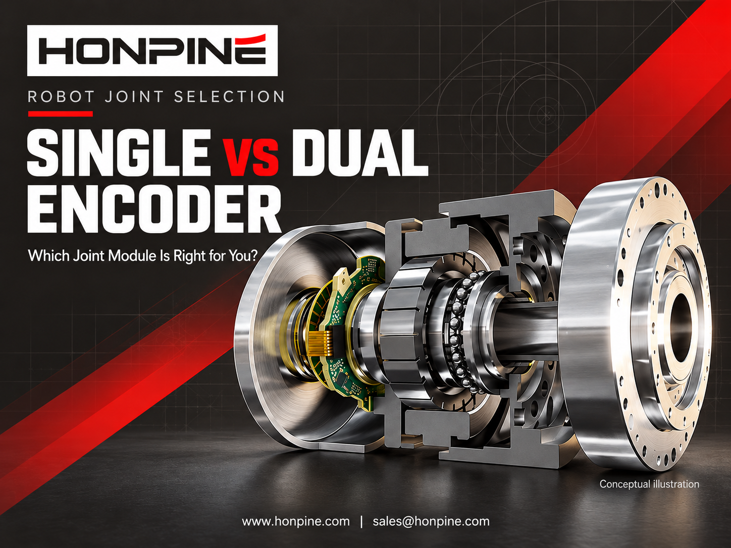
 What’s the Difference Between Single and Dual Encoder Robot Joint Modules?Does your robot need a dual encoder joint module, or is a single encoder enough? The answer depends on positioning requirements, transmission behavior, force control strategy and budget. This guide compares motor-side and output-side feedback, explains where dual encoders can improve control, and examines their costs and limitations. Learn when a single encoder can meet your needs and when additional output feedback is worth considering.
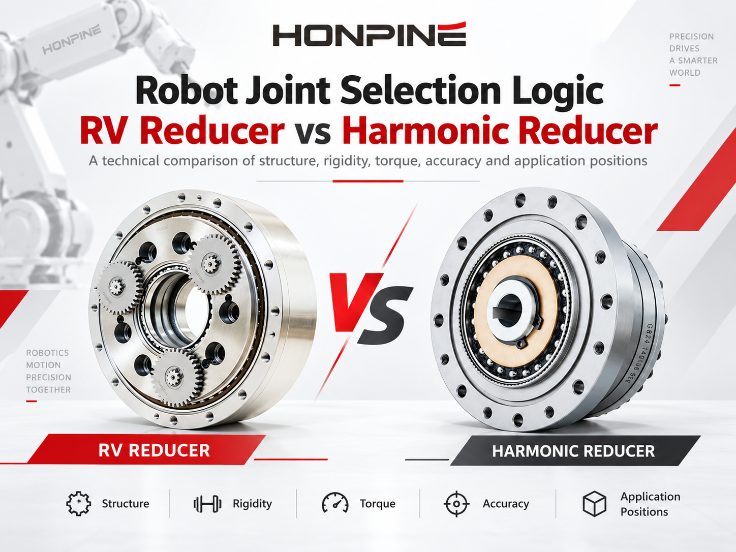
 RV vs Harmonic Reducer: How to Choose the Right Gearbox for Robot Joints?RV vs harmonic reducer: which gearbox is right for your robot joint? The answer depends on torque, rigidity, accuracy, installation space and operating conditions. This guide compares their working principles and five key performance factors, then explains how to evaluate joint loads, reducer life, temperature and lubrication. Whether you are designing a robot base, shoulder, elbow or wrist, use these considerations to match the reducer to the requirements of each joint.
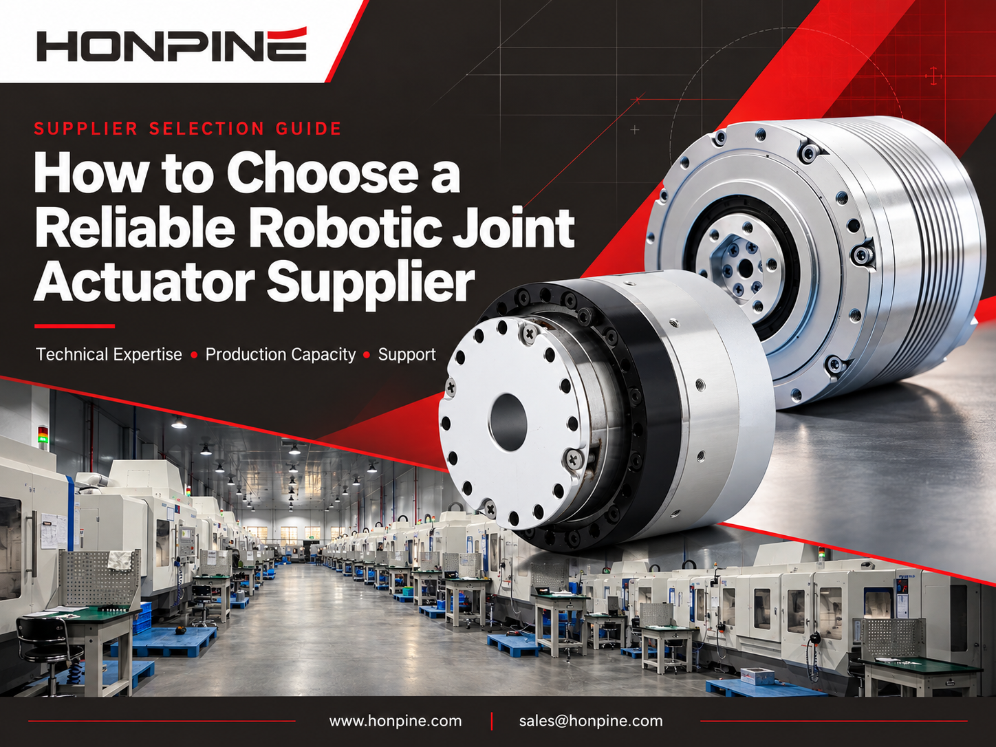
 How to Find a Reliable Robotic Joint Actuator Supplier?Choosing the right robotic joint actuator supplier is essential for reliable performance, smooth integration and long-term project success. Beyond product specifications, you need to understand a supplier’s technical expertise, production capacity and after-sales support. In this guide, Allen Li, Founder of HONPINE, explains how to assess these three factors when sourcing harmonic and planetary joint actuators for robotics and industrial automation.
 Harmonic Reducer vs. Harmonic Rotary Actuator: Which Is Better for CNC Machine Tools?Choosing between a harmonic reducer and a harmonic rotary actuator is an important decision in CNC machine tool design. Both solutions offer high-precision motion control, but they differ in integration, installation requirements, rigidity, and system flexibility. For CNC fourth-axis rotary tables and compact five-axis machining systems, selecting the right harmonic drive can significantly influence machine performance. In this article, HONPINE Technical Director Theodore Li compares harmonic reducers and harmonic rotary actuators to help engineers identify the most suitable solution for their CNC applications.
 How to Choose Harmonic Joint Actuators for a 7-DOF Robotic Arm?I'm Theodore Li, Technical Director at HONPINE. Choosing harmonic joint actuators for a 7-DOF robotic arm starts with the torque, weight, and installation needs of each joint. This guide uses a TCHL 20 shoulder and TCHL 14 wrist configuration as an example, then explores torque sensing, compliant control, and HAG Series considerations for demanding robotic applications.
Double Click
We provide harmonic drive reducer,planetary reducer,robot joint motor,robot rotary actuators,RV gear reducer,robot end effector,dexterous robot hand
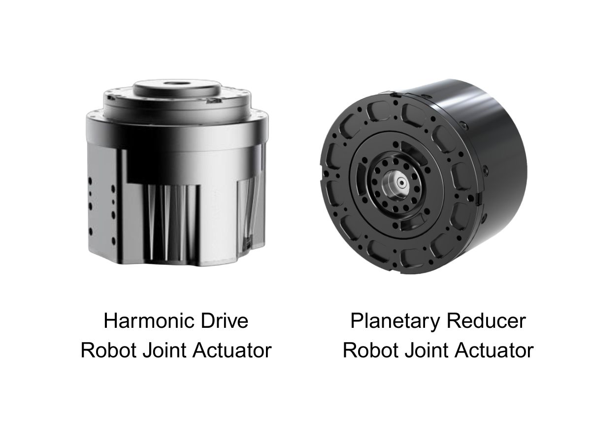
 What is robot joint actuator?How to Choose the Best Robot Rotary Joint Actuator?In core robot joint transmission solutions, planetary and harmonic rotary actuators each have their own strengths. Choosing the right type based on application requirements is essential to achieve the optimal balance between performance and cost.
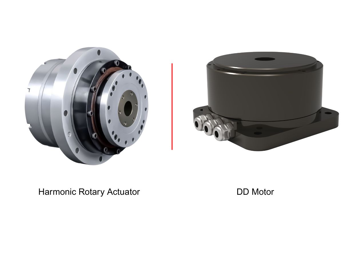
 DD Motors VS Harmonic Rotary ActuatorsThis article provides an in-depth comparison between Direct Drive (DD) motors and harmonic rotary actuators, covering their transmission principles, advantages and disadvantages, and typical application fields.
 OMG Ultra Compact Harmonic Drive Joint Module with Built-in Torque SensorHONPINE TCHL series harmonic drive joint module is a game-changing product that achieves disruptive improvements in multiple aspects such as lightweight design, integration level, and connection convenience. This article will analyze its revolutionary enhancements with you.
 How to Calculate Torque for a Harmonic Rotary Actuator in a Flipping Mechanism?How much torque does a harmonic rotary actuator need to flip a 10 kg load through 180 degrees? The answer depends on more than weight. Center-of-gravity offset, load inertia, acceleration and operating frequency all affect actuator selection. In this guide, Theodore Li, Technical Director at HONPINE, explains the calculation process using a horizontal-axis flipping example and outlines the checks needed for peak torque, continuous operation, output speed and bearing loads.
 What’s the Difference Between Single and Dual Encoder Robot Joint Modules?Does your robot need a dual encoder joint module, or is a single encoder enough? The answer depends on positioning requirements, transmission behavior, force control strategy and budget. This guide compares motor-side and output-side feedback, explains where dual encoders can improve control, and examines their costs and limitations. Learn when a single encoder can meet your needs and when additional output feedback is worth considering.
 RV vs Harmonic Reducer: How to Choose the Right Gearbox for Robot Joints?RV vs harmonic reducer: which gearbox is right for your robot joint? The answer depends on torque, rigidity, accuracy, installation space and operating conditions. This guide compares their working principles and five key performance factors, then explains how to evaluate joint loads, reducer life, temperature and lubrication. Whether you are designing a robot base, shoulder, elbow or wrist, use these considerations to match the reducer to the requirements of each joint.
 How to Find a Reliable Robotic Joint Actuator Supplier?Choosing the right robotic joint actuator supplier is essential for reliable performance, smooth integration and long-term project success. Beyond product specifications, you need to understand a supplier’s technical expertise, production capacity and after-sales support. In this guide, Allen Li, Founder of HONPINE, explains how to assess these three factors when sourcing harmonic and planetary joint actuators for robotics and industrial automation.
 Harmonic Reducer vs. Harmonic Rotary Actuator: Which Is Better for CNC Machine Tools?Choosing between a harmonic reducer and a harmonic rotary actuator is an important decision in CNC machine tool design. Both solutions offer high-precision motion control, but they differ in integration, installation requirements, rigidity, and system flexibility. For CNC fourth-axis rotary tables and compact five-axis machining systems, selecting the right harmonic drive can significantly influence machine performance. In this article, HONPINE Technical Director Theodore Li compares harmonic reducers and harmonic rotary actuators to help engineers identify the most suitable solution for their CNC applications.
 How to Choose Harmonic Joint Actuators for a 7-DOF Robotic Arm?I'm Theodore Li, Technical Director at HONPINE. Choosing harmonic joint actuators for a 7-DOF robotic arm starts with the torque, weight, and installation needs of each joint. This guide uses a TCHL 20 shoulder and TCHL 14 wrist configuration as an example, then explores torque sensing, compliant control, and HAG Series considerations for demanding robotic applications.
 AGV Suspension: Should You Choose a Balance Beam or a Spring-Loaded Steering Drive Unit?Choosing an AGV suspension system starts with the vehicle’s load range and floor conditions. Balance beams and spring-loaded steering drive units offer different approaches to maintaining wheel contact and managing wheel loads. This HONPINE guide compares both options and explains how to evaluate traction, suspension travel, installation space, and maintenance before choosing a configuration.
 Hollow Rotary Platform Motor Matching: A Complete GuideSelecting the right motor for a hollow rotary platform is essential for achieving precise positioning, stable operation, and efficient automation. This guide explains how to match servo motors, stepper motors, and brushless DC motors with hollow rotary platforms based on torque, speed, inertia, accuracy, and installation requirements. Explore practical motor selection guidelines, typical application combinations, and space-saving mounting solutions to find the right configuration for your automation project.
 Can Robots Feel Touch? HONPINE HAG Force-Controlled Harmonic Robot Joint MotorsCan robots respond to a gentle touch? The HONPINE HAG robot joint motor with torque sensor combines a harmonic reducer, integrated torque sensing, and closed-loop control to detect external forces and support smooth, compliant motion. In this article, HONPINE founder Allen Li demonstrates the module's response to light contact and hand-guided movement, explains its key force-control technologies, and shares the vision behind joint modules designed for practical industrial robotics.