








Why Are Servo Motors and Gear Reducers an Ideal Match?
What Are the Advantages of Servo Motors?
Servo motors offer three key advantages: fast response, high positioning precision, and excellent controllability. However, conventional servo motors typically deliver their rated power at relatively high speeds, with limited torque available directly at the motor shaft.
Many AC servo motors have rated speeds of approximately 1,500–3,000 rpm, while some high-speed models exceed 5,000 rpm. At a given mechanical power, torque decreases as rotational speed increases. For example, a 1 kW servo motor operating at 3,000 rpm produces approximately 3.2 N·m of rated torque.
This torque may be insufficient to directly drive a robot arm weighing tens of kilograms. Depending on the robot’s size and application, wrist joints can require peak torques of tens or even hundreds of newton-metres, while base joints may require several hundred newton-metres.
Could a servo motor be designed to deliver high torque at low speed? Yes—direct-drive torque motors are designed for this purpose. However, achieving the required torque can involve trade-offs in motor size, weight, cost, and thermal management. These factors can make direct drive challenging for robotic joints with strict space and weight constraints.
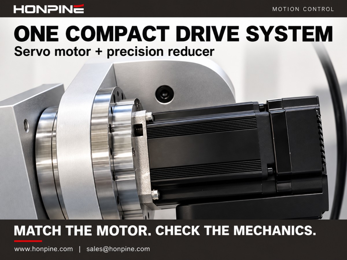
The central challenge is matching the motor’s operating characteristics to the load: the servo motor runs relatively fast, while the robotic joint often needs lower speed and higher torque. A gear reducer helps bridge this difference.
How Does a Gear Reducer Improve Servo Motor Performance?
A gear reducer does more than lower rotational speed. It also increases output torque, reduces the load inertia reflected to the motor, and improves theoretical output position resolution.
1. Lower Speed and Higher Output Torque
Ignoring losses, mechanical power remains approximately constant through a reducer. Reducing speed increases the available output torque in proportion to the reduction ratio. In practice, transmission efficiency must also be included:
Output torque = Motor torque × Reduction ratio × Transmission efficiency
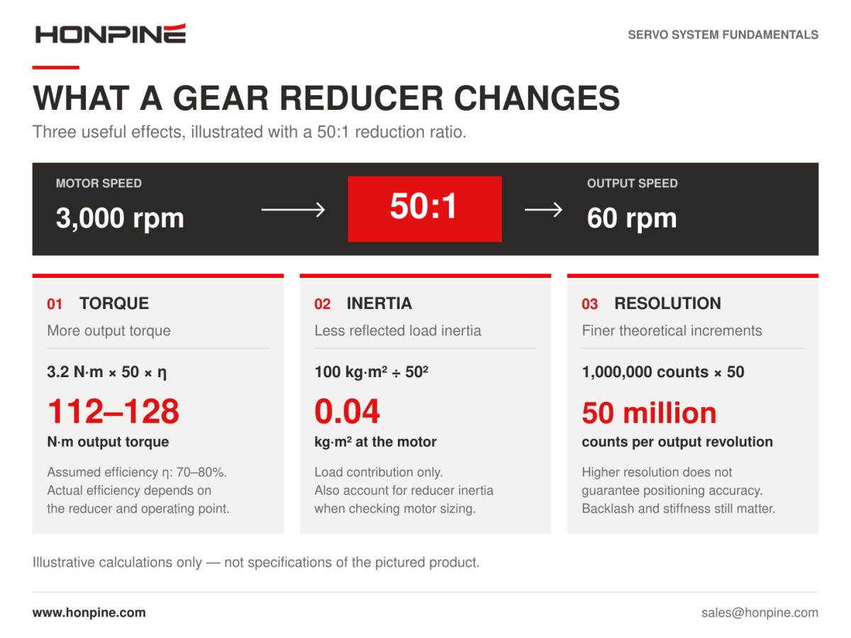
Consider a harmonic reducer with a reduction ratio of 50:1. With an input torque of 3.2 N·m and an assumed transmission efficiency of 70–80%, the calculated output torque is 3.2 × 50 × 0.70–0.80 = 112–128 N·m.
This illustrates how a compact servo motor can deliver substantially greater torque through a reducer. The actual output must still remain within the reducer’s rated, acceleration, and peak torque limits, and efficiency should be checked for the intended operating conditions.
2. Lower Reflected Load Inertia
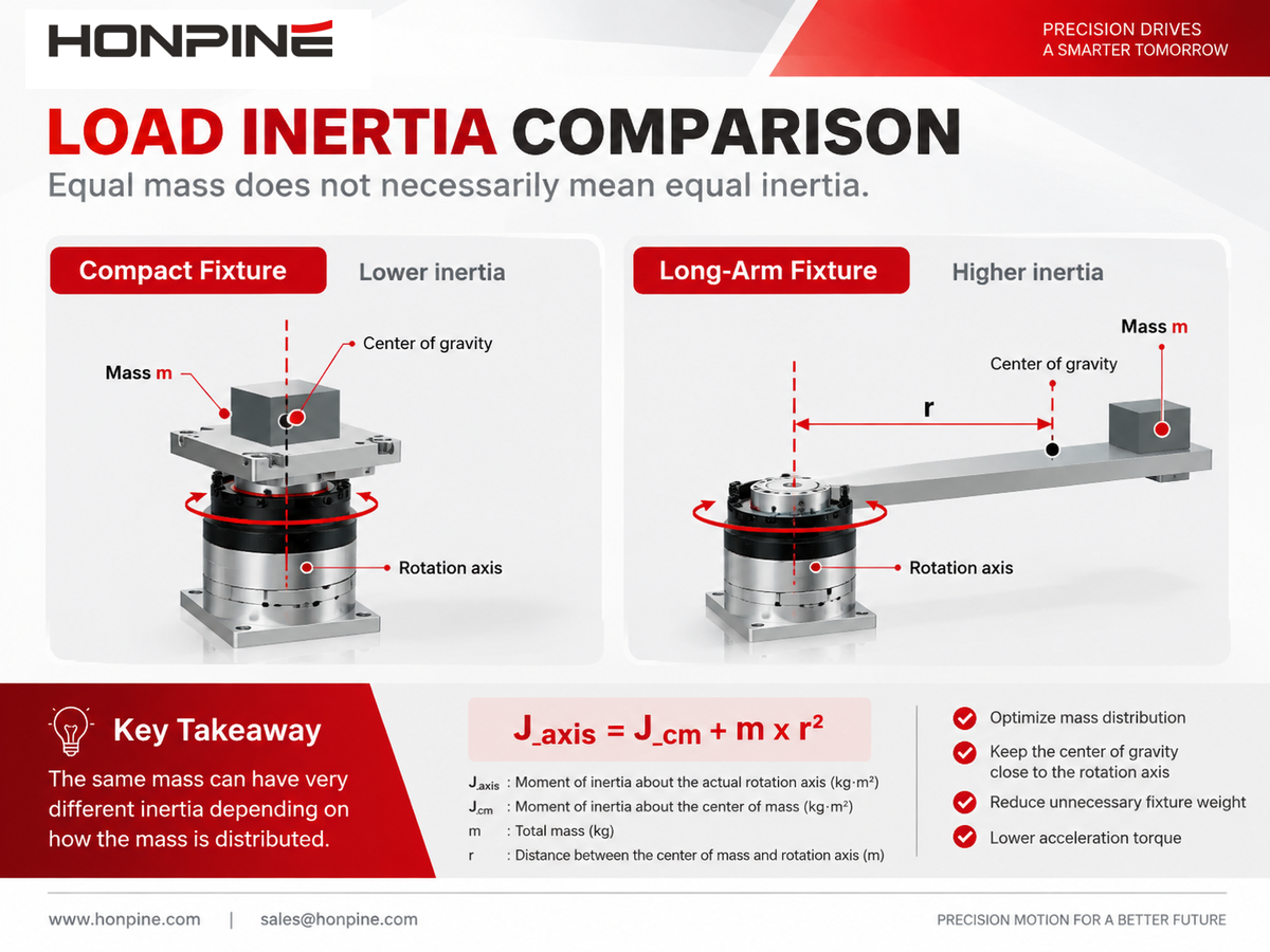
Another important function of a gear reducer is reducing the load inertia reflected to the motor shaft. The reflected load inertia is divided by the square of the reduction ratio:
Reflected load inertia = Load inertia ÷ Reduction ratio²
For example, consider a rotary table with a load inertia of 100 kg·m². With a 50:1 reducer, the load inertia reflected to the motor becomes 100 ÷ 50² = 0.04 kg·m²—a reduction by a factor of 2,500.
This is a mathematical example of inertia reflection, rather than a complete motor-sizing calculation. Reducer inertia, required acceleration, friction, and operating speed must also be considered. Nevertheless, reducing reflected load inertia can make a demanding load easier for the servo system to control.
3. Finer Theoretical Output Position Resolution
The motor encoder has a fixed resolution. If it provides one million counts per motor revolution, direct drive provides one million counts per output revolution.
With a 50:1 reducer, the motor completes 50 revolutions for every output revolution. The system therefore provides an equivalent 50 million encoder counts per output revolution, improving theoretical output position resolution by a factor of 50.
However, resolution is not the same as positioning accuracy. Backlash, transmission error, elastic deformation, encoder accuracy, and control performance all influence the actual output position.
Together, torque multiplication, inertia reduction, and finer theoretical position resolution explain why gear reducers are widely paired with servo motors in robotics and automation.
What Makes a Servo Motor and Gear Reducer Work Well Together?
A successful combination requires more than matching a fast motor with a slower output. Inertia matching, backlash, and torsional stiffness all affect the performance of the complete system.
Inertia Matching: Can the Motor Control the Load?
Servo performance is influenced by the relationship between the inertia reflected to the motor shaft and the motor’s rotor inertia. A high inertia ratio can make rapid acceleration, deceleration, and settling more difficult, particularly when the transmission has limited stiffness.
An inertia ratio of approximately 10:1 or less is often used as an initial sizing guideline, while more demanding response requirements may lead designers to target around 5:1 or lower. These are starting points, not universal limits. The acceptable ratio depends on the servo drive, motor, mechanical structure, motion profile, and tuning.
A lower inertia ratio is not inherently a cause of instability, nor does it guarantee optimal performance. The complete system must be evaluated.
The reduction ratio acts as an adjustment factor: increasing it reduces reflected load inertia rapidly, while decreasing it increases the inertia seen by the motor. Inertia matching is therefore an important consideration when selecting a reduction ratio.
Backlash: What Happens When the Direction Reverses?
Backlash is the mechanical clearance that creates lost movement when the transmission reverses direction. With excessive backlash, the motor can rotate through a small angle before the output begins to respond.
This delay can produce positioning errors, reversal impacts, and inconsistent motion. Precision applications therefore often require reducers with very low backlash or lost motion.
Depending on the model and measurement method, precision harmonic reducers and RV reducers can achieve specifications at or below one arcminute. Standard precision planetary reducers commonly have backlash specifications of approximately 3–10 arcminutes, while higher-precision models can also reach the one-arcminute range.
One arcminute equals 1/60 of a degree. Always check the selected manufacturer’s specification, test conditions, and terminology: backlash, lost motion, and hysteresis are related characteristics but should not be treated as interchangeable measurements.
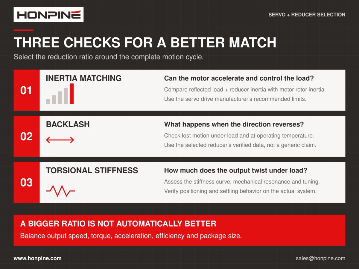
Torsional Stiffness: How Much Does the Transmission Twist?
Torsional stiffness describes a transmission’s resistance to angular deformation under torque. If stiffness is insufficient, the output can twist elastically when the load changes.
When position feedback comes only from the motor side, the controller may indicate that the commanded position has been reached even though the output has deflected. Mechanical compliance can also introduce resonances that limit control gains and make tuning more difficult.
Achieving low backlash and high torsional stiffness together can increase design complexity, manufacturing requirements, and cost. A suitable reducer balances these characteristics with load capacity, service life, and the application’s performance requirements.
Is a Higher Reduction Ratio Always Better?
It is tempting to assume that a higher reduction ratio is always preferable because it increases output torque. In practice, the ratio must balance torque, speed, acceleration, inertia, and installation constraints.
For a given motor acceleration, a higher reduction ratio produces a lower output acceleration. Applications requiring rapid starts, stops, or frequent reciprocating motion therefore need careful evaluation of the motor’s torque-speed capability and the complete acceleration profile.
A higher ratio also changes the relationship between motor inertia and reflected load inertia. Although the load inertia seen by the motor decreases, this alone does not guarantee better dynamic performance. Reducer inertia, mechanical stiffness, friction, and controller tuning remain important.
Output speed is another limitation. Excessive reduction can prevent the mechanism from reaching its required operating speed, increasing cycle time and reducing productivity.
Depending on the reducer design, achieving a higher ratio may also involve additional transmission stages, changes in size, or higher cost. These trade-offs vary between harmonic, RV, and planetary reducers and should be checked for the selected product.
The selection principle is straightforward: meet the required output speed, torque, and positioning performance while keeping the motor and reflected load inertia compatible with the control system. The final ratio should be supported by calculations and application testing.
How Should You Choose Between Harmonic, RV, and Planetary Reducers?
Harmonic reducers are often selected for compact, lightweight joints requiring high reduction ratios and precise positioning. RV reducers are commonly evaluated for heavily loaded joints, robot shoulders, and bases where stiffness and load capacity are priorities. Precision planetary reducers offer a practical balance of performance, efficiency, and cost in many general automation applications.
These are useful starting points, but the final choice should follow the load requirements of the individual axis. A more detailed comparison of the three reducer types will be covered in a separate article.
Conclusion
The servo system provides responsive, precise motion control, while the gear reducer adapts the motor’s speed and torque to the load. Their complementary roles make them an effective combination for many robotic joints and automation mechanisms.
The strongest results come from selecting them as a complete drive system. Matching torque, speed, inertia, backlash, and stiffness helps engineers achieve the required motion performance within the available space, weight, and budget.
Read More
Learn more about the story of HONPINE and industry trends related to precision transmission.
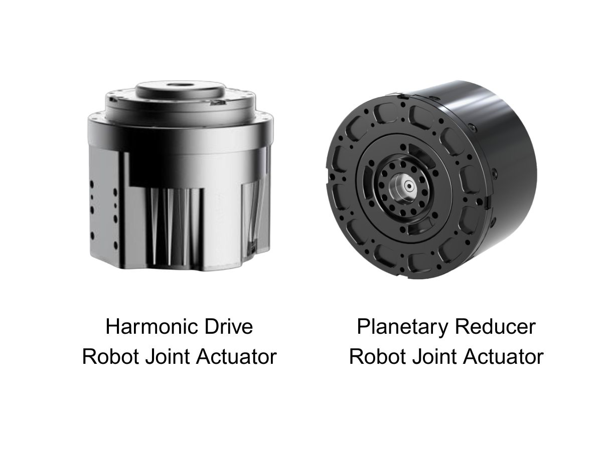
 What is robot joint actuator?How to Choose the Best Robot Rotary Joint Actuator?In core robot joint transmission solutions, planetary and harmonic rotary actuators each have their own strengths. Choosing the right type based on application requirements is essential to achieve the optimal balance between performance and cost.
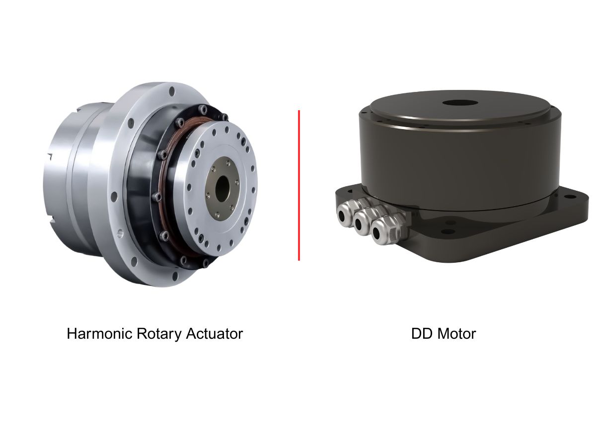
 DD Motors VS Harmonic Rotary ActuatorsThis article provides an in-depth comparison between Direct Drive (DD) motors and harmonic rotary actuators, covering their transmission principles, advantages and disadvantages, and typical application fields.
 OMG Ultra Compact Harmonic Drive Joint Module with Built-in Torque SensorHONPINE TCHL series harmonic drive joint module is a game-changing product that achieves disruptive improvements in multiple aspects such as lightweight design, integration level, and connection convenience. This article will analyze its revolutionary enhancements with you.
 The Role of Harmonic Drive Gears in Achieving 5–10 μm Accuracy in Dental Milling MachinesA dental milling machine is a CNC machining system used to directly process digital dental models into restorations such as crowns, bridges, veneers, inlays, and implant abutments. Dental milling machines require far higher operational accuracy and motion stability than ordinary equipment. This article explains how harmonic drive gear help dental milling machines achieve stable, continuous, and controllable operation.
 Why Are Harmonic Rotary Actuators Perfect for Medical Equipment?Harmonic rotary actuators (typically integrated systems consisting of a harmonic drive reducer, frameless torque motor, encoder, and optional brake) are regarded as key components in medical equipment. The core reason is that they simultaneously meet the most stringent medical requirements for precision, compact size, safety, and controllability. The following explanation is structured from three perspectives: technical characteristics, application scenarios, and medical value.
 High-Precision RV Reducers Perfectly Matched for Walking RobotsThe walking axis of a robot is a core component for power transmission and support. RV reducers provide extremely high rigidity, precision, and torque while maintaining a compact size and exceptional reliability, making them an ideal match for the demanding requirements of walking robot joints in terms of load capacity, impact resistance, and precision.
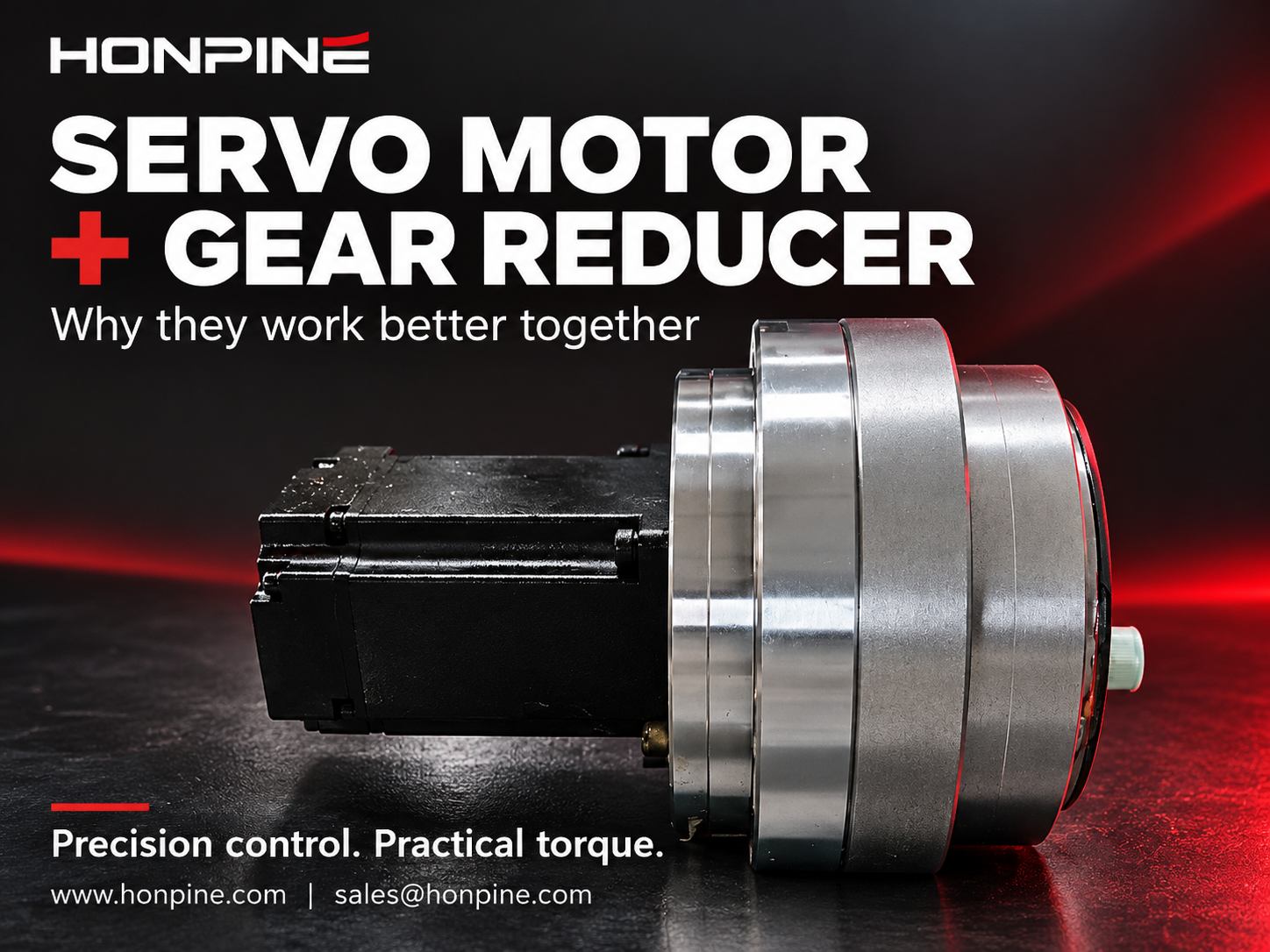
 Why Are Servo Motors and Gear Reducers an Ideal Match?Servo motors provide fast, precise motion control, while gear reducers adapt their speed and torque to the load. This guide explains how servo motors and gear reducers work together through torque multiplication, reflected inertia reduction and finer theoretical position resolution. Learn how inertia matching, backlash, torsional stiffness and reduction ratio influence performance in robotics and industrial automation.
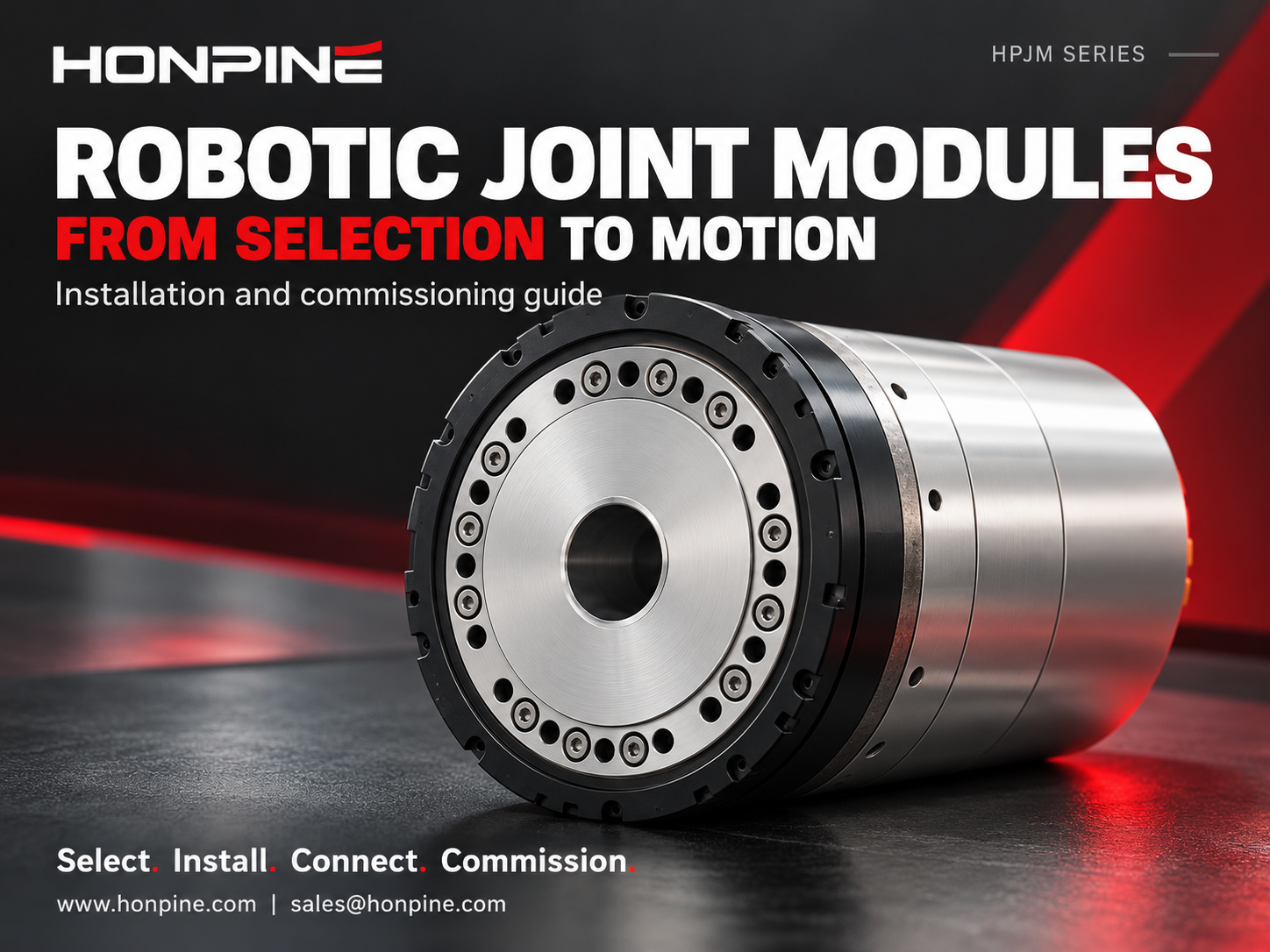
 How to Select and Use Robotic Joint Modules?How do you take robotic joint modules from selection to controlled motion? Using the HONPINE HPJM harmonic joint module as an example, Technical Director Theodore Li explains the key steps in mechanical installation, electrical wiring, CAN and EtherCAT configuration, and control commissioning. Learn what to confirm before integration and how to approach setup so each joint can respond correctly to your controller.
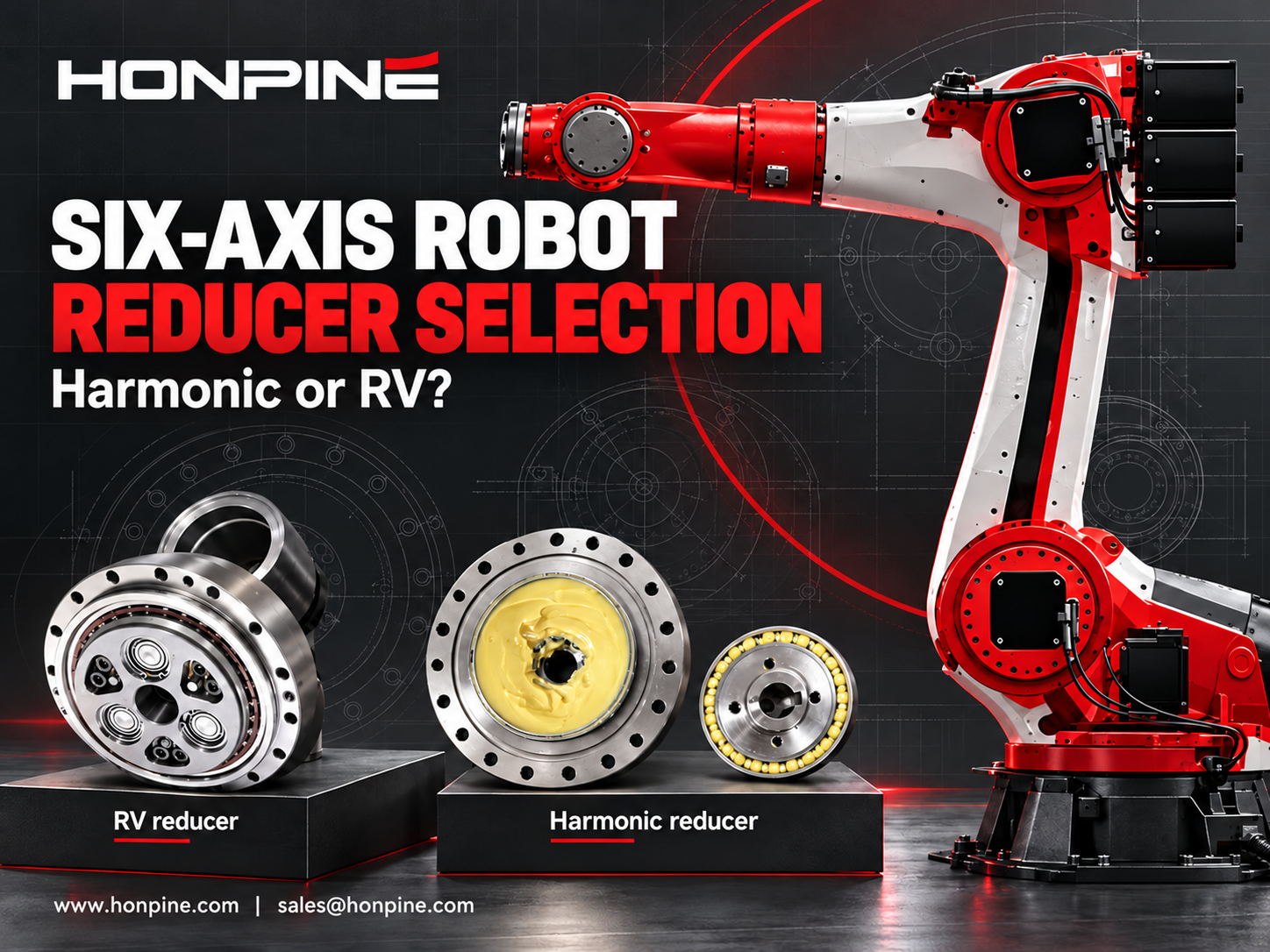
 How to Select Harmonic and RV Reducers for Each Axis of a Six-Axis Robot?What determines whether a six-axis robot joint needs a harmonic reducer or an RV reducer? The answer depends on torque, inertia, impact loads, bearing loads and installation space. This guide explains how to evaluate harmonic and RV reducers for the base, shoulder, elbow and wrist, with practical checks for stiffness, backlash and service life. Use the requirements of each axis to select a suitable reducer configuration.
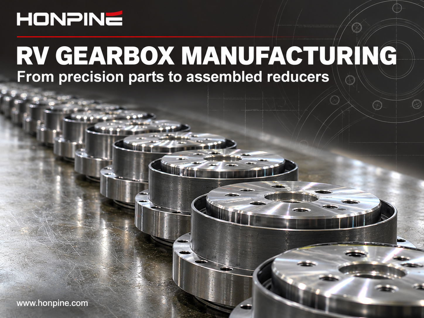
 Top 7 RV Reducer Gearbox Manufacturers: Why Does Nabtesco Still Dominate?What sets RV reducer gearbox manufacturers apart, and why does Nabtesco remain a benchmark in this market? RV reducer production demands precise component machining, careful assembly and extensive engineering know-how. This article introduces seven manufacturers across RV reducers and related transmission technologies, examines the strengths behind Nabtesco's position, and explores HONPINE's development capabilities to help you understand the supplier landscape.
 How to Calculate Torque for a Harmonic Rotary Actuator in a Flipping Mechanism?How much torque does a harmonic rotary actuator need to flip a 10 kg load through 180 degrees? The answer depends on more than weight. Center-of-gravity offset, load inertia, acceleration and operating frequency all affect actuator selection. In this guide, Theodore Li, Technical Director at HONPINE, explains the calculation process using a horizontal-axis flipping example and outlines the checks needed for peak torque, continuous operation, output speed and bearing loads.
 Why Are Harmonic Reducers Suitable for CNC Machine Tool Rotary Tables?Why choose harmonic reducers for CNC rotary tables? Accurate indexing depends on more than the motor: backlash, torsional stiffness and torque capacity all affect how reliably a rotary table holds its position during machining. This guide explains the key transmission requirements of fourth and fifth axis rotary tables, explores common machine tool applications, and introduces HONPINE harmonic reducer configurations for different installation and load requirements.
Double Click
We provide harmonic drive reducer,planetary reducer,robot joint motor,robot rotary actuators,RV gear reducer,robot end effector,dexterous robot hand
 What is robot joint actuator?How to Choose the Best Robot Rotary Joint Actuator?In core robot joint transmission solutions, planetary and harmonic rotary actuators each have their own strengths. Choosing the right type based on application requirements is essential to achieve the optimal balance between performance and cost.
 DD Motors VS Harmonic Rotary ActuatorsThis article provides an in-depth comparison between Direct Drive (DD) motors and harmonic rotary actuators, covering their transmission principles, advantages and disadvantages, and typical application fields.
 OMG Ultra Compact Harmonic Drive Joint Module with Built-in Torque SensorHONPINE TCHL series harmonic drive joint module is a game-changing product that achieves disruptive improvements in multiple aspects such as lightweight design, integration level, and connection convenience. This article will analyze its revolutionary enhancements with you.
 Why Are Servo Motors and Gear Reducers an Ideal Match?Servo motors provide fast, precise motion control, while gear reducers adapt their speed and torque to the load. This guide explains how servo motors and gear reducers work together through torque multiplication, reflected inertia reduction and finer theoretical position resolution. Learn how inertia matching, backlash, torsional stiffness and reduction ratio influence performance in robotics and industrial automation.
 How to Select and Use Robotic Joint Modules?How do you take robotic joint modules from selection to controlled motion? Using the HONPINE HPJM harmonic joint module as an example, Technical Director Theodore Li explains the key steps in mechanical installation, electrical wiring, CAN and EtherCAT configuration, and control commissioning. Learn what to confirm before integration and how to approach setup so each joint can respond correctly to your controller.
 How to Select Harmonic and RV Reducers for Each Axis of a Six-Axis Robot?What determines whether a six-axis robot joint needs a harmonic reducer or an RV reducer? The answer depends on torque, inertia, impact loads, bearing loads and installation space. This guide explains how to evaluate harmonic and RV reducers for the base, shoulder, elbow and wrist, with practical checks for stiffness, backlash and service life. Use the requirements of each axis to select a suitable reducer configuration.
 Top 7 RV Reducer Gearbox Manufacturers: Why Does Nabtesco Still Dominate?What sets RV reducer gearbox manufacturers apart, and why does Nabtesco remain a benchmark in this market? RV reducer production demands precise component machining, careful assembly and extensive engineering know-how. This article introduces seven manufacturers across RV reducers and related transmission technologies, examines the strengths behind Nabtesco's position, and explores HONPINE's development capabilities to help you understand the supplier landscape.
 How to Calculate Torque for a Harmonic Rotary Actuator in a Flipping Mechanism?How much torque does a harmonic rotary actuator need to flip a 10 kg load through 180 degrees? The answer depends on more than weight. Center-of-gravity offset, load inertia, acceleration and operating frequency all affect actuator selection. In this guide, Theodore Li, Technical Director at HONPINE, explains the calculation process using a horizontal-axis flipping example and outlines the checks needed for peak torque, continuous operation, output speed and bearing loads.
 Why Are Harmonic Reducers Suitable for CNC Machine Tool Rotary Tables?Why choose harmonic reducers for CNC rotary tables? Accurate indexing depends on more than the motor: backlash, torsional stiffness and torque capacity all affect how reliably a rotary table holds its position during machining. This guide explains the key transmission requirements of fourth and fifth axis rotary tables, explores common machine tool applications, and introduces HONPINE harmonic reducer configurations for different installation and load requirements.
 What’s the Difference Between Single and Dual Encoder Robot Joint Modules?Does your robot need a dual encoder joint module, or is a single encoder enough? The answer depends on positioning requirements, transmission behavior, force control strategy and budget. This guide compares motor-side and output-side feedback, explains where dual encoders can improve control, and examines their costs and limitations. Learn when a single encoder can meet your needs and when additional output feedback is worth considering.
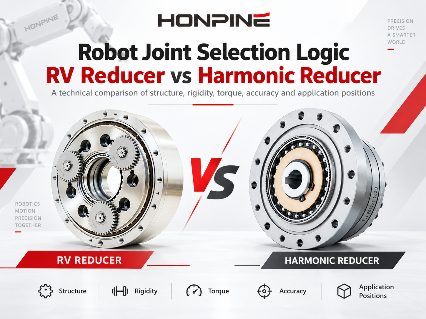
 RV vs Harmonic Reducer: How to Choose the Right Gearbox for Robot Joints?RV vs harmonic reducer: which gearbox is right for your robot joint? The answer depends on torque, rigidity, accuracy, installation space and operating conditions. This guide compares their working principles and five key performance factors, then explains how to evaluate joint loads, reducer life, temperature and lubrication. Whether you are designing a robot base, shoulder, elbow or wrist, use these considerations to match the reducer to the requirements of each joint.
 How to Find a Reliable Robotic Joint Actuator Supplier?Choosing the right robotic joint actuator supplier is essential for reliable performance, smooth integration and long-term project success. Beyond product specifications, you need to understand a supplier’s technical expertise, production capacity and after-sales support. In this guide, Allen Li, Founder of HONPINE, explains how to assess these three factors when sourcing harmonic and planetary joint actuators for robotics and industrial automation.