







Robot Joint Module Selection Guide: How to Choose the Right Joint Module Based on Load, Precision, Force Control, and Motion Requirements
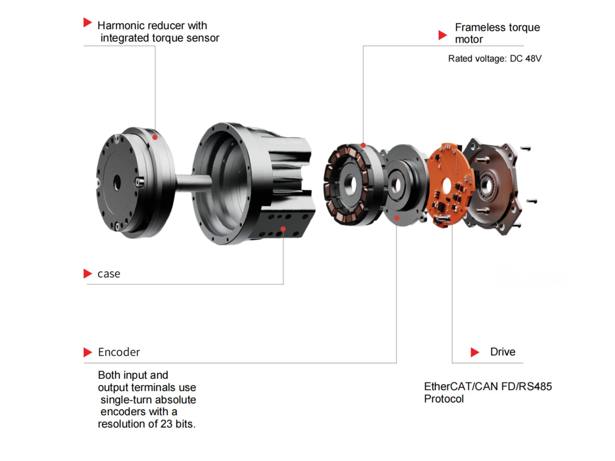
Integrated robot joint modules are core motion units in collaborative robots, humanoid robots, industrial robotic arms, and other intelligent robotic systems. Typically, they integrate key components such as a motor, reducer, encoder, servo drive, torque sensor, and electromagnetic brake into a compact motion unit.
Choosing the right robot joint module directly affects not only output torque, rotational speed, and positioning accuracy but also the robot's dynamic response, force control performance, structural design, operational stability, and overall manufacturing cost.
Unlike selecting an individual motor or reducer, robot joint module selection requires a comprehensive evaluation of dynamic performance, transmission structure, position feedback, torque measurement, mechanical installation, electrical interfaces, thermal management, and long-term reliability. This is particularly important for collaborative and humanoid robots, where different joints have significantly different load conditions, motion frequencies, control requirements, and safety considerations.
Based on practical application experience with HONPINE's lightweight, high-precision TCHL series robot joint modules, this guide examines six essential aspects of robot joint module selection to help robotics engineers establish a systematic approach to joint design and integration.
1. Dynamic Performance: How to Determine Torque, Speed, and Inertia Requirements
Dynamic performance is the foundation of robot joint module selection. It determines whether a joint can meet the actual requirements for payload, rotational speed, acceleration, and dynamic response.
The most important parameters to evaluate include continuous rated torque, peak torque, output speed, and inertia matching.
1.1 How Should Continuous Rated Torque and Peak Torque Be Distinguished?
Torque is one of the most important parameters when selecting a robot joint module. However, engineers must distinguish between continuous rated torque and peak torque rather than judging a module solely by its maximum torque rating.
Continuous Rated Torque refers to the torque a joint module can deliver continuously under specified operating conditions and thermal limits. It is particularly relevant to applications such as continuous material handling, posture holding, grinding, and other long-duration operations.
When calculating the required joint torque, engineers should consider:
The weight of the joint itself and its associated gravitational torque.
The gravitational torque generated by the end effector and external payload.
Acceleration and deceleration torque during joint movement.
Mechanical friction and other transmission resistance.
Dynamic coupling effects between multiple joints.
During preliminary selection, an appropriate safety margin should also be reserved based on load variations, motion frequency, installation orientation, and operating conditions. For example, a margin of 25%–35% can serve as an initial design reference, but it should not be treated as a universal requirement. Final sizing should be verified against the actual joint load profile and thermal equilibrium conditions.
Peak Torque is primarily used for short-duration dynamic operations, such as rapid robot acceleration, posture transitions, transient load changes, and brief impact events.
It is important to understand that peak torque does not mean the joint module can maintain this output for extended periods. Engineers should verify the allowable peak torque duration, repetition frequency, and associated thermal limitations.
The torque capacity of the motor, reducer, and mechanical housing should also be checked separately. The component with the lowest allowable torque establishes the practical torque limit of the complete joint assembly.
This distinction is particularly important for high-dynamic joints in humanoid robot legs, quadruped robot hips, and heavy-duty robotic arms.
1.2 How Should Output Speed and Gear Ratio Be Matched?
The output speed of a robot joint module is primarily determined by the motor speed and reduction ratio:
Output Speed ≈ Motor Speed ÷ Reduction Ratio
Increasing the reduction ratio generally increases output torque but reduces output speed. It may also affect backdrivability, dynamic response, and the equivalent inertia of the transmission system.
In addition, motor speed cannot be considered independently of the power supply. For 24V or 48V DC-powered joint modules, motor back EMF increases as rotational speed rises. If the available DC bus voltage is insufficient, the available current and output torque may decrease in the high-speed operating range.
Therefore, engineers should evaluate more than the no-load maximum speed. Important parameters include:
Continuous output torque at rated speed.
Available torque at maximum operating speed.
Performance variations under different supply voltages.
The influence of reduction ratio on dynamic response and backdrivability.
For humanoid robot joints that require rapid swinging, frequent acceleration, and repeated stopping, matching output speed and torque is particularly important.
1.3 Why Does Inertia Matching Affect Joint Control Stability?
Inertia matching is an important but sometimes overlooked factor in robot joint module selection.
An unsuitable relationship between external load inertia and the inertia of the drive system can increase control difficulty and lead to low-speed vibration, motion overshoot, mechanical oscillation, or reduced dynamic tracking performance.
For collaborative robots, humanoid robots, and robotic arms requiring precise motion tracking and compliant control, engineers should evaluate the motor rotor inertia, reducer ratio, load inertia, and actual motion trajectories through dynamic analysis.
It is also important to remember that a reducer changes the equivalent inertia of the load when referred to the motor side. Therefore, system compatibility should not be determined simply by comparing load inertia with motor rotor inertia. The transmission ratio, control bandwidth, and actual operating conditions must also be considered.
2. Transmission Structure and Positioning Accuracy: Harmonic vs. Planetary Robot Joint Modules
The reducer is a critical transmission component within a robot joint module. Its design directly influences output torque, transmission accuracy, torsional stiffness, impact resistance, and service life.
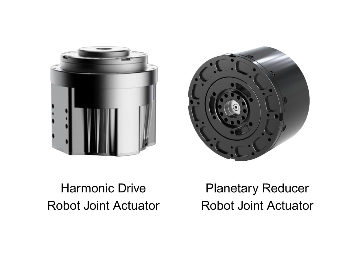
Harmonic reducers and planetary reducers are two commonly used transmission solutions in robot joint modules. Neither is universally superior; the appropriate choice depends on the robot's motion requirements and operating conditions.
2.1 Characteristics and Applications of Harmonic Drive Joint Modules
Harmonic reducers feature a compact structure, high reduction ratios, and low transmission backlash. These characteristics make them suitable for robot joints with limited installation space and demanding positioning accuracy requirements.
Harmonic transmission is widely used in collaborative robots, humanoid robots, and precision robotic arms.
Key characteristics include:
Compact construction for space-constrained joint designs.
Low transmission backlash for improved positioning accuracy.
A wide range of reduction ratios for high-torque output.
Suitability for precision positioning and certain force-controlled applications.
However, harmonic reducers rely on elastic deformation of the flexspline. Their torsional stiffness, impact load capacity, and fatigue life must therefore be evaluated according to the specific model and operating conditions.
For applications involving frequent impacts, heavy reciprocating loads, or substantial dynamic load variations, long-term reliability should be carefully verified.
2.2 Characteristics and Applications of Planetary Gear Joint Modules
Planetary reducers transmit power through a system consisting of a sun gear, planet gears, and an internal ring gear. They generally offer strong load-bearing capacity, good structural rigidity, and high transmission efficiency.
Planetary transmission can be advantageous in heavy-duty industrial robots, quadruped robots, and joints exposed to substantial external impacts.
Key characteristics include:
Multiple gear-meshing points that help distribute transmitted loads.
Good load capacity and impact resistance.
Suitability for relatively high-load and dynamic operating conditions.
Good durability when properly designed and lubricated.
However, conventional planetary reducers generally have some transmission backlash. Its magnitude depends on gear manufacturing accuracy, assembly methods, preload structures, and manufacturing processes.
For applications requiring high positioning accuracy and compliant force control, engineers should verify the actual backlash and overall transmission performance of the complete joint module.
2.3 How to Select the Right Transmission Structure for Different Robot Applications
The transmission type alone should not determine the selection. Engineers should also consider joint load, motion frequency, impact intensity, and control requirements.
For example:
Collaborative robots: Focus on transmission backlash, backdrivability, and force control performance.
Humanoid robots: Consider torque density, weight, dynamic response, and impact resistance.
Quadruped robots: Prioritize dynamic loading, impact capacity, and fatigue life.
Heavy-duty industrial robotic arms: Evaluate continuous torque, stiffness, and long-term operating reliability.
For applications requiring a combination of low backlash, high torsional stiffness, and strong load-bearing capacity, high-precision planetary transmission solutions with preload and backlash elimination designs may also be worth considering.
Engineers do not need to limit their selection to conventional transmission structures.
2.4 Which Accuracy Parameters Should Be Evaluated in a Robot Joint Module?
The actual positioning accuracy of a robot joint is not equivalent to the nominal accuracy of its reducer alone.
The overall accuracy of a joint module is also affected by motor encoders, output encoders, reducer backlash, torsional deformation, bearing support, flange machining, and assembly tolerances.
During selection, engineers should pay particular attention to:
Output-side transmission backlash.
Output-side repeatability.
Torsional stiffness and load-induced deformation.
Output flange face runout.
Flatness and dimensional accuracy of mounting surfaces.
Among these parameters, actual output feedback accuracy and angular displacement under load are particularly important.
For precision assembly, medical robotics, and precision manufacturing equipment, engineers should request actual test data and clearly defined testing conditions rather than relying solely on individual component specifications.
3. Encoders and Torque Sensors: How to Achieve High-Precision Force Control in Robot Joints
If the reducer determines the transmission performance of a joint, encoders and torque sensors determine the feedback information available to the control system.
For conventional point-to-point motion, position feedback may be sufficient. However, collaborative robots, humanoid robots, and systems interacting with their environments often require more advanced feedback than motor-side position and current measurements alone can provide.
3.1 What Is the Difference Between Single-Encoder and Dual-Encoder Joint Modules?
Robot joint modules commonly use either a single-encoder semi-closed-loop architecture or a dual-encoder full-closed-loop architecture.
Single-Encoder Architecture
In a single-encoder design, the encoder is typically installed on the motor side to detect rotor position and calculate the theoretical output position of the joint.
This architecture is relatively simple and cost-effective, making it suitable for conventional point-to-point positioning and applications with less demanding output-side feedback requirements.
However, because the encoder is installed before the reducer, it cannot directly measure the actual output position. As a result, it cannot directly compensate for reducer backlash, torsional deformation, and certain transmission errors.
Dual-Encoder Architecture
A dual-encoder design uses two encoders: one on the motor side and another on the output side.
The motor-side encoder supports motor commutation and speed control, while the output-side encoder measures the actual joint output angle.
By comparing the input-side and output-side positions, the control system can obtain a more accurate understanding of the transmission system's actual motion.
Dual-encoder architecture is particularly suitable for:
High-precision position control.
Stable low-speed operation.
High-dynamic motion tracking.
Robot joints requiring transmission deformation compensation.
Flexible control systems with demanding position feedback requirements.
For high-precision robot joints, an architecture with output-side absolute position feedback is generally worth prioritizing.
3.2 Why Do Advanced Robot Joints Need Output-Side Torque Sensors?
Torque feedback is an important foundation for high-precision force control.
There are two common approaches to obtaining joint torque information: estimating torque from motor current and directly measuring torque using an independent torque sensor.
Motor current-based estimation typically calculates electromagnetic torque using the motor torque constant and measured current. This approach does not require an additional torque sensor and is relatively cost-effective.
However, the motor's electromagnetic torque is not necessarily equal to the actual output torque of the joint.
Factors such as reducer friction, transmission losses, inertial torque, and temperature variations can affect the final output torque. Consequently, current-based estimation has limitations in applications requiring highly accurate force feedback.
In comparison, a torque sensor installed between the reducer output and the joint flange can directly measure the torque transmitted through the transmission system. This provides a measurement that more closely represents the actual interaction between the robot and its external environment.
For example, HONPINE's TCHL series robot joint modules adopt an output-side torque sensing architecture. This configuration is designed for robotic systems that require real-time detection of joint load variations.
Typical applications include:
Collaborative robots and human-robot interaction.
Precision assembly and insertion operations.
Surface grinding and constant-force control.
Adaptive posture control in humanoid robots.
Exoskeleton robots and compliant assistive devices.
It is important to note that output-side torque sensing does not eliminate every influence from the transmission system. Sensor accuracy, mechanical installation, calibration, and control algorithms also affect the final measurement results.
3.3 Which Technical Specifications Matter When Selecting a Torque Sensor?
When selecting a torque sensor, engineers should evaluate more than its rated measurement range. Dynamic response and long-term stability are equally important.
Key parameters include:
Measurement Range: The sensor should cover the normal operating torque and expected dynamic loads without operating too close to its overload limits or using an unnecessarily large measurement range.
Measurement Accuracy: Evaluate nonlinearity, repeatability, hysteresis, and overall measurement error rather than relying on a single accuracy specification.
Zero Stability and Temperature Drift: Temperature changes during long-term operation may cause zero-point deviation, affecting continuous force control and low-torque measurement.
Sampling Frequency and Bandwidth: High-dynamic interaction and collision detection require sufficient sensor sampling capability and system control bandwidth to prevent feedback delays.
Noise Level: Excessive measurement noise may cause fluctuations in force control commands and reduce motion smoothness.
For material handling, fixed-position motion, and other applications without precise force interaction requirements, a joint module without an independent torque sensor may be sufficient. This can help reduce hardware costs and system complexity.
4. Mechanical Structure and Installation Compatibility: How to Match Joint Modules to Robot Designs
A robot joint module is not merely a power transmission unit; it is also an integral part of the robot's mechanical structure.
Its dimensions, installation interfaces, hollow-shaft design, and weight distribution all influence the overall robot design.
4.1 How Should Hollow-Shaft Design and Module Weight Be Evaluated?
For humanoid robots, multi-joint robotic arms, and complex robotic systems, hollow-shaft joint modules offer significant wiring advantages.
Power cables, communication cables, sensor wires, and other connections can be routed through the hollow center, reducing external cable tangling and potential motion interference.
For applications requiring continuous rotation, slip rings may also be considered depending on the system design. Engineers should verify that the hollow diameter, cable routing, and rotation range are compatible.
Module weight is another important consideration.
In multi-joint robots, the mass of joints closer to the end effector increases the load and inertia experienced by upstream joints. Therefore, reducing the weight of distal joints while maintaining sufficient torque and stiffness can help reduce the drive requirements of upstream joints and improve overall dynamic response and energy efficiency.
During selection, engineers should compare module weight, rated torque, peak torque, and torque density rather than simply choosing the highest torque rating.
4.2 Is an Electromagnetic Brake Necessary for Robot Joint Modules?
An electromagnetic brake is primarily used to hold a joint in position when the power supply is disconnected or the drive system stops operating. It helps prevent unintended movement caused by gravity.
Brake configuration should be carefully considered for humanoid robot knee and hip joints, vertical robotic arms, and other joints carrying gravitational loads.
A commonly used solution is a spring-applied, electrically released electromagnetic brake. It engages when power is removed and releases when energized.
When selecting a brake, engineers should verify:
Rated holding torque.
Brake release voltage and power consumption.
Engagement and release response times.
Brake service life.
Compatibility with the joint's installation space.
It is important to understand that the primary function of a brake is static holding. It does not replace dynamic braking control provided by the servo drive, nor should it automatically be assumed capable of handling every emergency dynamic impact.
For horizontal joints with light loads, the need for a brake can be evaluated according to the application and safety requirements.
4.3 Which Installation Dimensions Should Be Verified?
The mechanical installation compatibility of a robot joint module directly affects transmission accuracy and operational reliability.
During the selection stage, engineers should confirm:
Mounting flange diameter and hole pattern.
Locating pilot dimensions.
Mounting screw specifications and effective engagement depth.
Front, rear, or side mounting configurations.
Flatness, parallelism, and roundness requirements of mating surfaces.
Recommended screw tightening torque and assembly sequence.
Maximum allowable output rotation and limit configurations.
Particular attention should be paid to mounting surface accuracy, locating pilot compatibility, uniform screw tightening, and possible structural interference.
Improper installation may cause joint resistance, positioning deviations, or even mechanical damage.
Engineers should also verify the relationship between mechanical limits, software limits, and cable rotation ranges to prevent overtravel, collisions, and cable damage.
5. Electrical and Control Systems: How to Select Drive Architecture, Supply Voltage, and Communication Protocols
The electrical specifications and communication protocols of a robot joint module determine its compatibility with the robot's main control system. They also directly influence multi-axis synchronization, real-time performance, and commissioning efficiency.
5.1 How to Choose Between 24V and 48V Robot Joint Modules
The most common supply voltages for robot joint modules are 24V and 48V DC.
At the same electrical power level, increasing the supply voltage reduces the required current. This helps minimize resistive losses and voltage drops across cables and connectors.
As a result, 48V power systems can offer advantages for multi-joint robots, high-power drives, and battery-powered mobile robotic platforms.
However, a 48V joint module is not necessarily better for every application.
Actual selection should consider:
The robot's DC bus voltage.
The allowable operating voltage range of the module.
Maximum and continuous current requirements.
Drive voltage ratings.
Battery discharge capability.
Cable length and voltage drop.
For humanoid robots and mobile platforms, engineers should also evaluate standby power consumption, peak current demand, and battery operating time.
5.2 What Is the Difference Between Integrated and External Servo Drives?
Robot joint modules can generally be divided into two architectures according to how the servo drive is installed: integrated-drive and external-drive configurations.
Integrated-Drive Joint Modules
In an integrated-drive design, the servo drive is installed inside the joint module. This creates a compact assembly with relatively simple external wiring and reduced system integration complexity.
Key advantages include:
High integration and efficient use of installation space.
Fewer external connections.
Easier modular design and system integration.
Suitability for lightweight and space-constrained robots.
However, integrated drives also place higher demands on internal thermal management, sealing, and electromagnetic compatibility.
External-Drive Joint Modules
In an external-drive design, the servo drive is installed separately from the motor and transmission assembly.
This provides greater flexibility in drive installation and thermal management. It also allows engineers to select or replace drive units according to different application requirements.
Key advantages include:
Independent thermal management for the drive.
Easier maintenance and replacement.
Suitability for certain high-power or specialized control applications.
Greater flexibility in electrical layout and system architecture.
However, external-drive configurations require additional planning for power cables, encoder cables, and communication wiring, which increases integration work.
Therefore, integrated-drive designs are not necessarily superior to external-drive solutions.
Integrated drives are attractive for robots requiring compact dimensions, lightweight construction, and simplified wiring. External drives may be more suitable when flexible drive configuration, independent cooling, or specialized control interfaces are required.
5.3 How to Choose Between EtherCAT, CAN FD, and RS485
Communication protocols determine how joint modules exchange commands and feedback data with the robot's main controller.
Common options include EtherCAT, CAN FD, and RS485.
EtherCAT: Offers high real-time performance and synchronization capabilities. It is suitable for multi-axis coordination, high-speed motion, and precision positioning, making it a common choice for industrial robots and high-performance multi-joint systems.
CAN FD: An enhanced version of conventional CAN with increased data transmission capability. It is suitable for distributed joint control and mobile or humanoid robot systems requiring higher communication efficiency.
RS485: Offers relatively simple wiring and good noise immunity. It is commonly used for industrial control and status communication. Its actual real-time performance depends on the communication protocol, network topology, and controller implementation.
During selection, engineers should confirm not only which communication protocols are supported but also whether the module is compatible with the target main controller.
Complete communication documentation, object dictionaries, control commands, and status feedback definitions should also be available.
5.4 Which Control Modes Should a Robot Joint Module Support?
Different robot applications require different control modes.
Common options include:
Position Control: For point-to-point positioning, trajectory tracking, and repetitive motion.
Velocity Control: For constant-speed rotation and continuous movement.
Torque Control: For output torque regulation and force-controlled applications.
Cyclic Synchronous Position Mode: For synchronized trajectory control across multiple joints.
Cyclic Synchronous Torque Mode: For high-dynamic control systems requiring real-time torque commands.
For collaborative and humanoid robots, engineers should pay particular attention to whether the joint module supports multiple control modes, including position, velocity, and torque control.
Smooth transitions between control modes are also important.
In addition, engineers should verify the position, velocity, and current control loop architecture, as well as functions such as following-error monitoring, overcurrent protection, and communication fault handling.
6. Thermal Management and Long-Term Reliability: How to Ensure Stable Joint Module Operation
During long-term operation, robot joint modules are affected by motor heating, reducer friction, ambient temperature, and variations in operating loads.
Therefore, engineers should evaluate thermal equilibrium, service life, and environmental adaptability in addition to initial performance specifications.
6.1 Why Are Temperature Rise and Thermal Equilibrium Important?
Motors and servo drives generate heat during operation, while friction inside the reducer also contributes to thermal losses.
If the joint operates under high loads or at high motion frequencies for extended periods without sufficient heat dissipation, excessive temperature rise may occur. This can result in reduced output torque, drive derating, or thermal protection shutdowns.
During selection, engineers should verify:
Whether the module uses natural cooling or assisted cooling.
Temperature monitoring for the motor and drive.
Temperature rise curves under continuous loading.
Time required to reach thermal equilibrium.
Derating behavior when temperature limits are approached.
Actual output capability under elevated ambient temperatures.
For high-frequency joints in humanoid robot knees, quadruped robot hips, and industrial robotic arms, long-duration temperature data is particularly important.
Short-duration performance tests alone are not sufficient to establish continuous operating capability.
6.2 How to Evaluate Reducer Service Life and Lubrication
The reducer is one of the most important components affecting the long-term reliability of a robot joint module.
Engineers should evaluate its rated service life, lubrication method, maintenance requirements, and actual operating conditions.
For harmonic reducers, important considerations include flexspline fatigue life, lubrication conditions, and the effects of impact loads.
For planetary reducers, attention should be paid to gear meshing, bearing loads, tooth surface wear, and lubrication conditions.
If the supplier provides L10 life data, engineers should confirm the corresponding load, rotational speed, lubrication, and operating temperature conditions.
It is also important to understand that the rated or theoretical service life of a reducer is not necessarily the actual service life of the complete joint module. Motor bearings, encoders, brakes, sensors, and servo drives also affect overall system reliability.
6.3 How Should the IP Protection Rating Be Selected?
Different robotic operating environments require different levels of protection.
For example:
Indoor laboratories: Select an appropriate protection rating according to dust and liquid exposure.
Industrial workshops: Consider dust, oil contamination, and occasional liquid splashes.
Outdoor robots: Evaluate rain exposure, humidity, and temperature variations.
Special cleaning environments: Confirm protection requirements according to the cleaning method and liquid exposure conditions.
IP54 can serve as an initial reference for some industrial environments. However, its suitability depends on actual exposure to dust and water.
For outdoor, humid, or washdown applications, a higher protection rating may be necessary.
Engineers should also verify that connectors, cable interfaces, and installation locations provide appropriate protection rather than relying solely on the enclosure's IP rating.
7. Robot Joint Module Selection Process: From Application Requirements to Final Model Verification
After understanding the key technical parameters, engineers should establish a systematic selection process instead of choosing a product based on a single specification.
The following steps provide a practical reference.
Step 1: Define the Robot Application.
Identify the robot type, joint position, motion range, payload, operating frequency, and working environment.
Step 2: Calculate the Joint's Dynamic Requirements.
Calculate continuous torque, peak torque, output speed, acceleration, and load inertia based on the robot's mechanical structure and motion trajectories.
Step 3: Determine the Transmission Structure and Accuracy Requirements.
Select an appropriate harmonic or planetary transmission solution according to load, stiffness, backlash, backdrivability, and dynamic performance requirements.
Step 4: Determine the Feedback and Force Control Configuration.
Select a single-encoder or dual-encoder architecture according to positioning accuracy requirements, and determine whether an output-side torque sensor is necessary.
Step 5: Complete Mechanical Compatibility Checks.
Confirm module diameter, length, hollow-shaft dimensions, flange interfaces, mounting configuration, weight, and brake requirements.
Step 6: Verify Electrical and Communication Compatibility.
Match the supply voltage, drive architecture, communication protocol, and control modes to ensure compatibility with the robot's main control system.
Step 7: Validate Thermal Performance and Long-Term Reliability.
Conduct actual load tests, temperature rise tests, dynamic motion tests, and necessary durability evaluations to confirm that the selected module meets the target operating conditions.
For collaborative robots, humanoid robots, and high-dynamic robotic arms, dynamic simulation, control parameter tuning, and prototype validation are recommended before finalizing the joint module model.
8. Frequently Asked Questions About Robot Joint Module Selection
Q1: Is a Higher Rated Torque Always Better When Selecting a Robot Joint Module?
Not necessarily. An oversized joint module may increase robot weight, inertia, energy consumption, and overall manufacturing cost.
The appropriate selection should be based on the actual load profile, continuous torque, peak torque, and required safety margin rather than simply choosing the highest available output torque.
Q2: Should Humanoid Robot Joints Use Harmonic or Planetary Reducers?
The choice depends on the position and operating requirements of each joint.
Harmonic transmission can be considered for joints requiring compact construction and low transmission backlash. High-performance planetary transmission may be suitable for joints exposed to substantial dynamic impacts and requiring strong load-bearing capacity.
The final decision should also consider torque density, weight, torsional stiffness, and control performance.
Q3: Do All Robot Joint Modules Need Torque Sensors?
No. For conventional point-to-point positioning, fixed-trajectory material handling, and applications without precise force interaction, motor current-based torque estimation may be sufficient.
For precision assembly, collision detection, human-robot collaboration, and compliant force control, an output-side torque sensor can provide more direct load feedback.
Q4: Is a Dual-Encoder Joint Module Always More Accurate Than a Single-Encoder Module?
A dual-encoder architecture can directly detect output-side position and provide feedback for transmission error compensation.
However, actual positioning accuracy also depends on encoder resolution, installation accuracy, reducer performance, mechanical stiffness, and control algorithms.
The number of encoders alone does not determine the final positioning accuracy of the robot.
Q5: Are Integrated-Drive Joint Modules More Suitable for Humanoid Robots?
Integrated-drive configurations offer high integration, simplified wiring, and compact construction, making them attractive for space-constrained humanoid robot designs.
However, engineers must also consider thermal management, electromagnetic compatibility, and maintenance requirements.
For certain high-power joints, external-drive configurations are also worth evaluating.
Conclusion: Effective Robot Joint Module Selection Requires a Balance of Performance, Structure, and Control
Robot joint module selection is not simply a matter of comparing rated torque, reduction ratio, and external dimensions. It requires a comprehensive evaluation of dynamic performance, transmission accuracy, feedback architecture, force control capability, mechanical installation, electrical interfaces, and long-term reliability based on the overall motion requirements of the robot.
For collaborative and humanoid robots, dual encoders, output-side torque sensors, and highly integrated joint modules can provide a more complete hardware foundation for high-precision position control and compliant force control.
For heavy-duty and high-dynamic robots, greater attention should be paid to torque density, torsional stiffness, impact resistance, and thermal equilibrium.
HONPINE's TCHL series robot joint modules are designed for lightweight robotic systems, high-precision motion control, and force interaction applications. With integrated transmission, position feedback, and torque sensing configurations, the series provides flexible joint solutions for different robotic requirements.
By evaluating the load, rotational speed, accuracy, and control requirements of each joint, robotics engineering teams can select suitable module configurations to support robot design, system integration, and reliable motion control.

About Author
Theodore Li serves as the Technical Director at HONPINE, overseeing the R&D strategy for replication products, guiding team selection, and managing both pre-sales and after-sales operations.

Read More
Learn more about the story of HONPINE and industry trends related to precision transmission.
 What is robot joint actuator?How to Choose the Best Robot Rotary Joint Actuator?In core robot joint transmission solutions, planetary and harmonic rotary actuators each have their own strengths. Choosing the right type based on application requirements is essential to achieve the optimal balance between performance and cost.
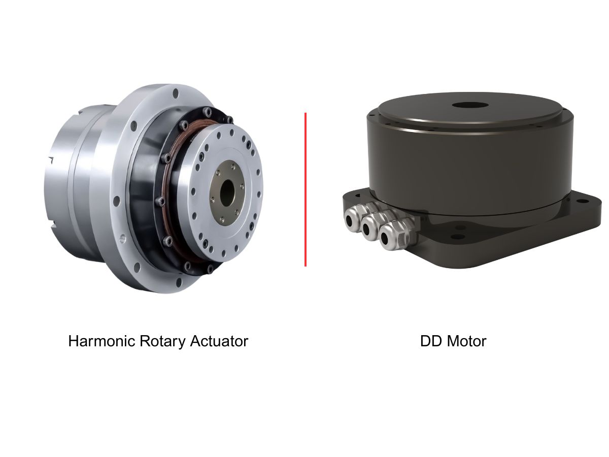
 DD Motors VS Harmonic Rotary ActuatorsThis article provides an in-depth comparison between Direct Drive (DD) motors and harmonic rotary actuators, covering their transmission principles, advantages and disadvantages, and typical application fields.
 OMG Ultra Compact Harmonic Drive Joint Module with Built-in Torque SensorHONPINE TCHL series harmonic drive joint module is a game-changing product that achieves disruptive improvements in multiple aspects such as lightweight design, integration level, and connection convenience. This article will analyze its revolutionary enhancements with you.
 The Role of Harmonic Drive Gears in Achieving 5–10 μm Accuracy in Dental Milling MachinesA dental milling machine is a CNC machining system used to directly process digital dental models into restorations such as crowns, bridges, veneers, inlays, and implant abutments. Dental milling machines require far higher operational accuracy and motion stability than ordinary equipment. This article explains how harmonic drive gear help dental milling machines achieve stable, continuous, and controllable operation.
 Why Are Harmonic Rotary Actuators Perfect for Medical Equipment?Harmonic rotary actuators (typically integrated systems consisting of a harmonic drive reducer, frameless torque motor, encoder, and optional brake) are regarded as key components in medical equipment. The core reason is that they simultaneously meet the most stringent medical requirements for precision, compact size, safety, and controllability. The following explanation is structured from three perspectives: technical characteristics, application scenarios, and medical value.
 High-Precision RV Reducers Perfectly Matched for Walking RobotsThe walking axis of a robot is a core component for power transmission and support. RV reducers provide extremely high rigidity, precision, and torque while maintaining a compact size and exceptional reliability, making them an ideal match for the demanding requirements of walking robot joints in terms of load capacity, impact resistance, and precision.
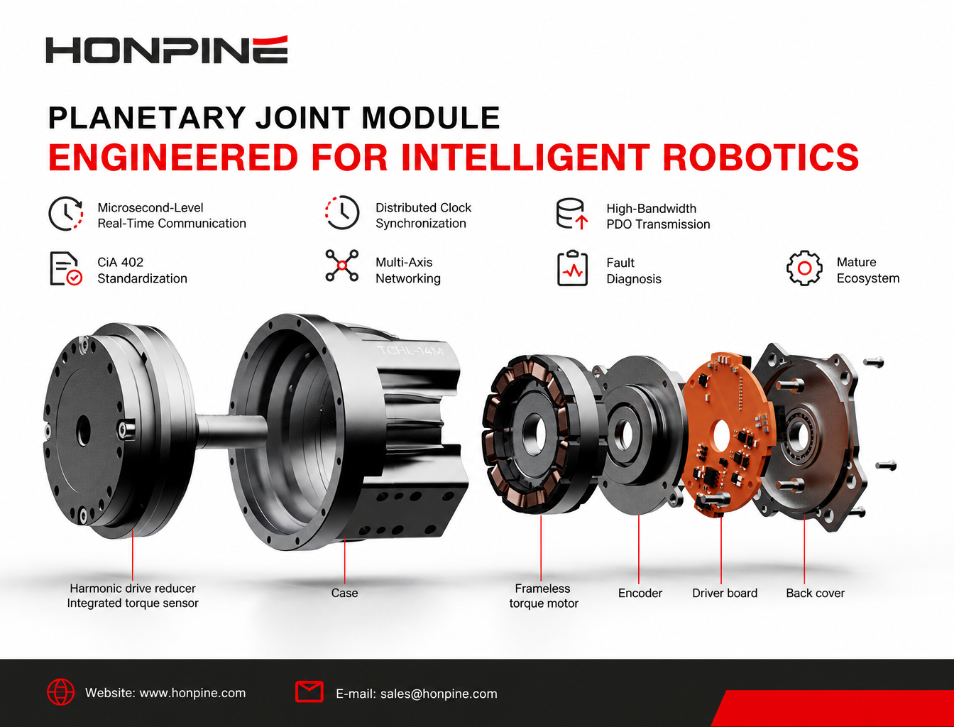
 Why Is EtherCAT Becoming the Mainstream Communication Bus for Robotic Joint Modules?Why is EtherCAT becoming the mainstream communication solution for intelligent robotic joint modules? This article explores seven key advantages, including microsecond-level real-time communication, Distributed Clock synchronization, CiA 402 standardization, high-bandwidth PDO transmission, multi-axis networking, fault diagnosis, and a mature development ecosystem. Learn how EtherCAT supports the advanced control requirements of humanoid robots, collaborative robots, and high-precision automation equipment.
 Robot Joint Module Selection Guide: How to Choose the Right Joint Module Based on Load, Precision, Force Control, and Motion RequirementsRobot Joint Module Selection Guide covering torque, speed, reducers, encoders, torque sensors, drive systems, and thermal management for collaborative and humanoid robots.
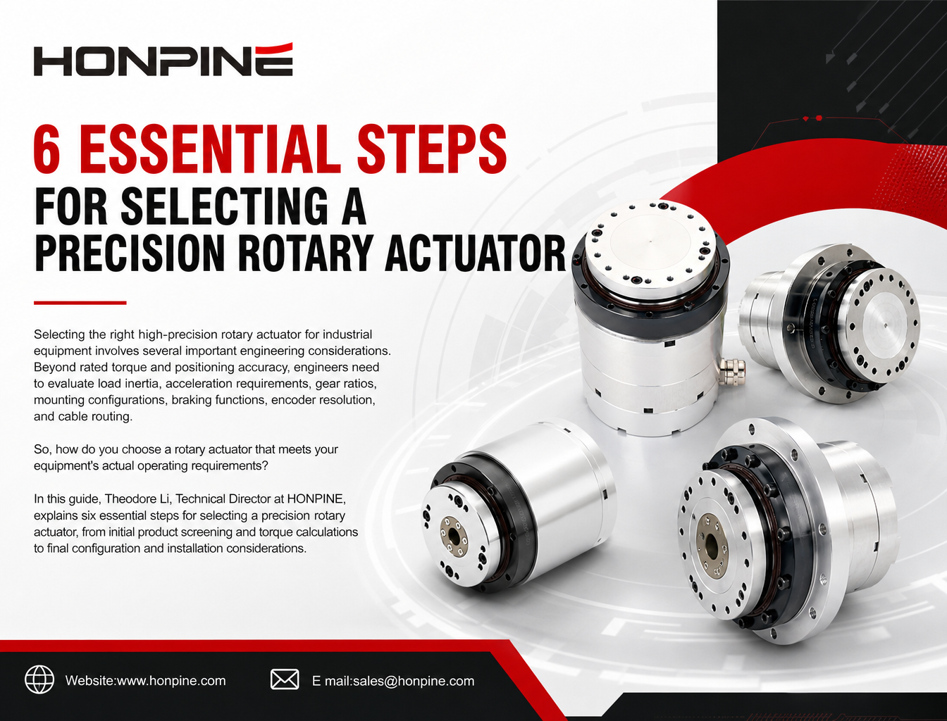
 How to Choose a High-Precision Rotary Actuator for Industrial Applications?Choosing the right precision rotary actuator requires more than checking rated torque. This guide explains how to calculate load torque, select the appropriate gear ratio, and evaluate structural configurations, mounting flanges, electromagnetic brakes, encoder resolution, and cable exit directions. Discover how HONPINE HAS, HAT, HAM, and HPG rotary actuator series meet different industrial motion control and precision positioning requirements.
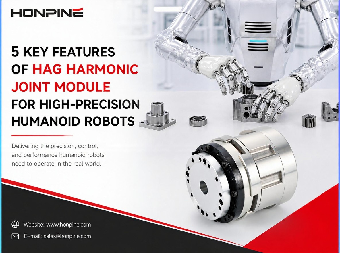
 What Kind of Robot Joint Module Should You Choose for High-Precision Humanoid Robot Control?As humanoid robots move beyond basic walking and demonstration tasks toward complex real-world applications, their joint modules must deliver more than just high torque. Precise positioning, accurate torque control, structural stiffness, and dynamic response all play important roles in performing delicate operations. So, what kind of joint module should you choose for a humanoid robot designed to handle high-precision tasks? In this article, Theodore Li, Technical Director at HONPINE, introduces the HAG Harmonic Joint Module and explains five key features that make it suitable for demanding humanoid robot applications.
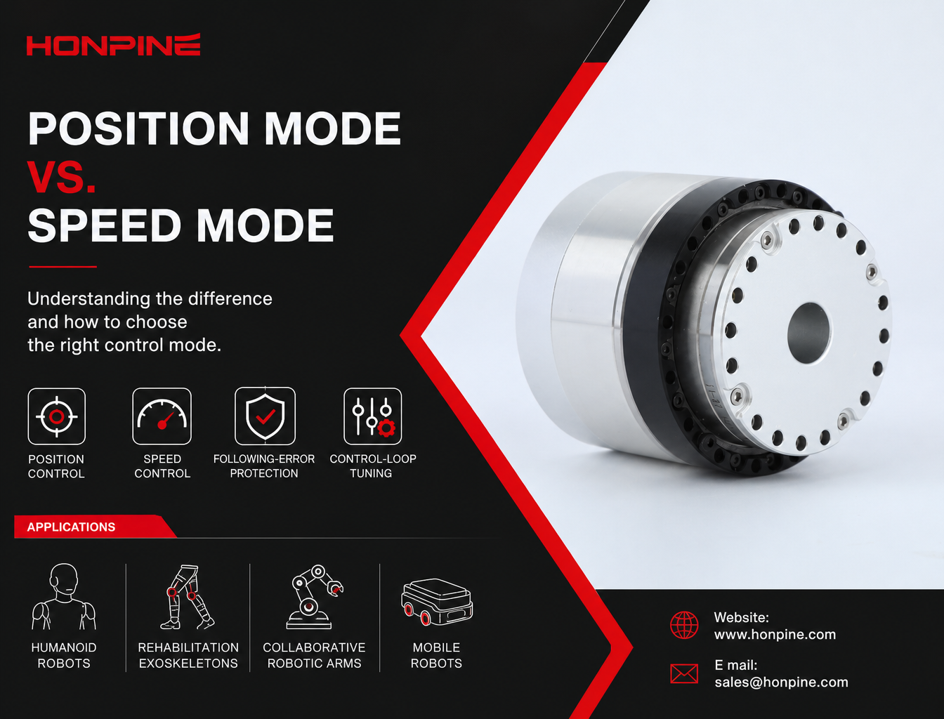
 HONPINE HPJM Harmonic Joint Motor: Position Mode vs. Speed Mode – How to Choose the Right Control Mode?Position mode and speed mode serve different motion-control requirements in robotic systems. Using the HONPINE HPJM harmonic joint motor as an example, this article explains their control architectures, operating principles, key differences, and application scenarios. From humanoid robot joints and rehabilitation exoskeletons to mobile robot drive wheels and continuous-rotation test systems, discover how to select the appropriate control mode based on motion objectives, mechanical loads, and system safety requirements.
 How Are Robot Industry Trends Shaping the Demand for Integrated Joint Modules and Hub Motors in 2026?The robotics industry is entering a new stage of development in 2026, with applications expanding from humanoid and quadruped robots to mobile manipulators, collaborative robots, and specialized robotic systems. As manufacturers move from prototype development toward commercialization and mass production, the demands on robotic drive systems are also changing. In this article, Allen Li, Founder of HONPINE, shares his observations on the evolving robotics market and explains why integrated joint modules and hub motors are becoming increasingly important for improving system integration, product consistency, and long-term operating reliability.
Double Click
We provide harmonic drive reducer,planetary reducer,robot joint motor,robot rotary actuators,RV gear reducer,robot end effector,dexterous robot hand
 What is robot joint actuator?How to Choose the Best Robot Rotary Joint Actuator?In core robot joint transmission solutions, planetary and harmonic rotary actuators each have their own strengths. Choosing the right type based on application requirements is essential to achieve the optimal balance between performance and cost.
 DD Motors VS Harmonic Rotary ActuatorsThis article provides an in-depth comparison between Direct Drive (DD) motors and harmonic rotary actuators, covering their transmission principles, advantages and disadvantages, and typical application fields.
 OMG Ultra Compact Harmonic Drive Joint Module with Built-in Torque SensorHONPINE TCHL series harmonic drive joint module is a game-changing product that achieves disruptive improvements in multiple aspects such as lightweight design, integration level, and connection convenience. This article will analyze its revolutionary enhancements with you.
 Why Is EtherCAT Becoming the Mainstream Communication Bus for Robotic Joint Modules?Why is EtherCAT becoming the mainstream communication solution for intelligent robotic joint modules? This article explores seven key advantages, including microsecond-level real-time communication, Distributed Clock synchronization, CiA 402 standardization, high-bandwidth PDO transmission, multi-axis networking, fault diagnosis, and a mature development ecosystem. Learn how EtherCAT supports the advanced control requirements of humanoid robots, collaborative robots, and high-precision automation equipment.
 Robot Joint Module Selection Guide: How to Choose the Right Joint Module Based on Load, Precision, Force Control, and Motion RequirementsRobot Joint Module Selection Guide covering torque, speed, reducers, encoders, torque sensors, drive systems, and thermal management for collaborative and humanoid robots.
 How to Choose a High-Precision Rotary Actuator for Industrial Applications?Choosing the right precision rotary actuator requires more than checking rated torque. This guide explains how to calculate load torque, select the appropriate gear ratio, and evaluate structural configurations, mounting flanges, electromagnetic brakes, encoder resolution, and cable exit directions. Discover how HONPINE HAS, HAT, HAM, and HPG rotary actuator series meet different industrial motion control and precision positioning requirements.
 What Kind of Robot Joint Module Should You Choose for High-Precision Humanoid Robot Control?As humanoid robots move beyond basic walking and demonstration tasks toward complex real-world applications, their joint modules must deliver more than just high torque. Precise positioning, accurate torque control, structural stiffness, and dynamic response all play important roles in performing delicate operations. So, what kind of joint module should you choose for a humanoid robot designed to handle high-precision tasks? In this article, Theodore Li, Technical Director at HONPINE, introduces the HAG Harmonic Joint Module and explains five key features that make it suitable for demanding humanoid robot applications.
 HONPINE HPJM Harmonic Joint Motor: Position Mode vs. Speed Mode – How to Choose the Right Control Mode?Position mode and speed mode serve different motion-control requirements in robotic systems. Using the HONPINE HPJM harmonic joint motor as an example, this article explains their control architectures, operating principles, key differences, and application scenarios. From humanoid robot joints and rehabilitation exoskeletons to mobile robot drive wheels and continuous-rotation test systems, discover how to select the appropriate control mode based on motion objectives, mechanical loads, and system safety requirements.
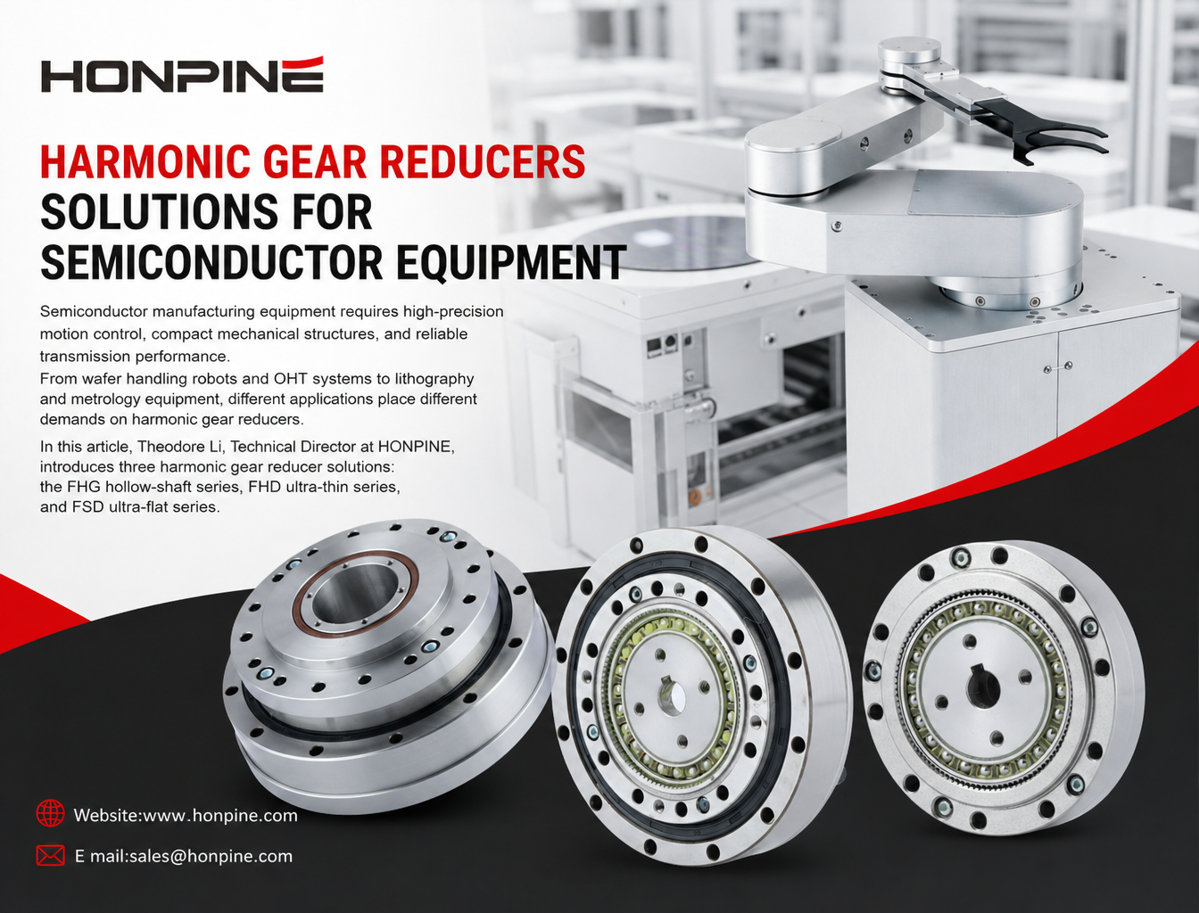
 3 Best Harmonic Gear Reducers for Semiconductor EquipmentSemiconductor manufacturing equipment requires high-precision motion control, compact mechanical structures, and reliable transmission performance. From wafer handling robots and OHT systems to lithography and metrology equipment, different applications place different demands on harmonic gear reducers. In this article, Theodore Li, Technical Director at HONPINE, introduces three harmonic gear reducer solutions: the FHG hollow-shaft series, FHD ultra-thin series, and FSD ultra-flat series. We will also examine 10 key technical parameters engineers should consider when selecting a harmonic gear reducer for semiconductor equipment, including rated torque, backlash, torsional rigidity, hollow shaft diameter, and permissible moment load.
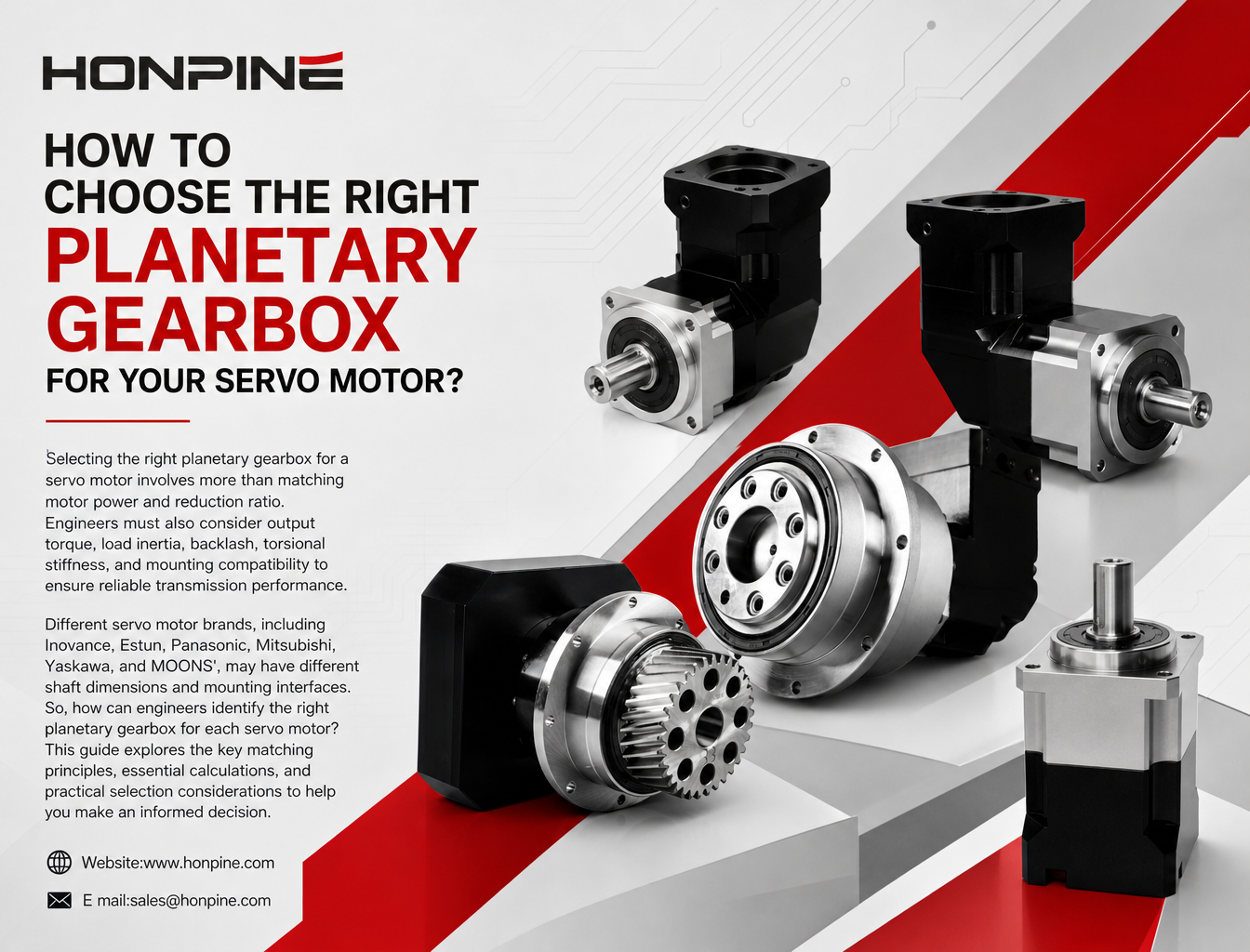
 How to Match Planetary Gearboxes with Servo Motors from 6 Major Brands?Selecting the right planetary gearbox for a servo motor involves more than matching motor power and reduction ratio. Engineers must also consider output torque, load inertia, backlash, torsional stiffness, and mounting compatibility to ensure reliable transmission performance. Different servo motor brands, including Inovance, Estun, Panasonic, Mitsubishi, Yaskawa, and MOONS', may have different shaft dimensions and mounting interfaces. So, how can engineers identify the right planetary gearbox for each servo motor? This guide explores the key matching principles, essential calculations, and practical selection considerations to help you make an informed decision.
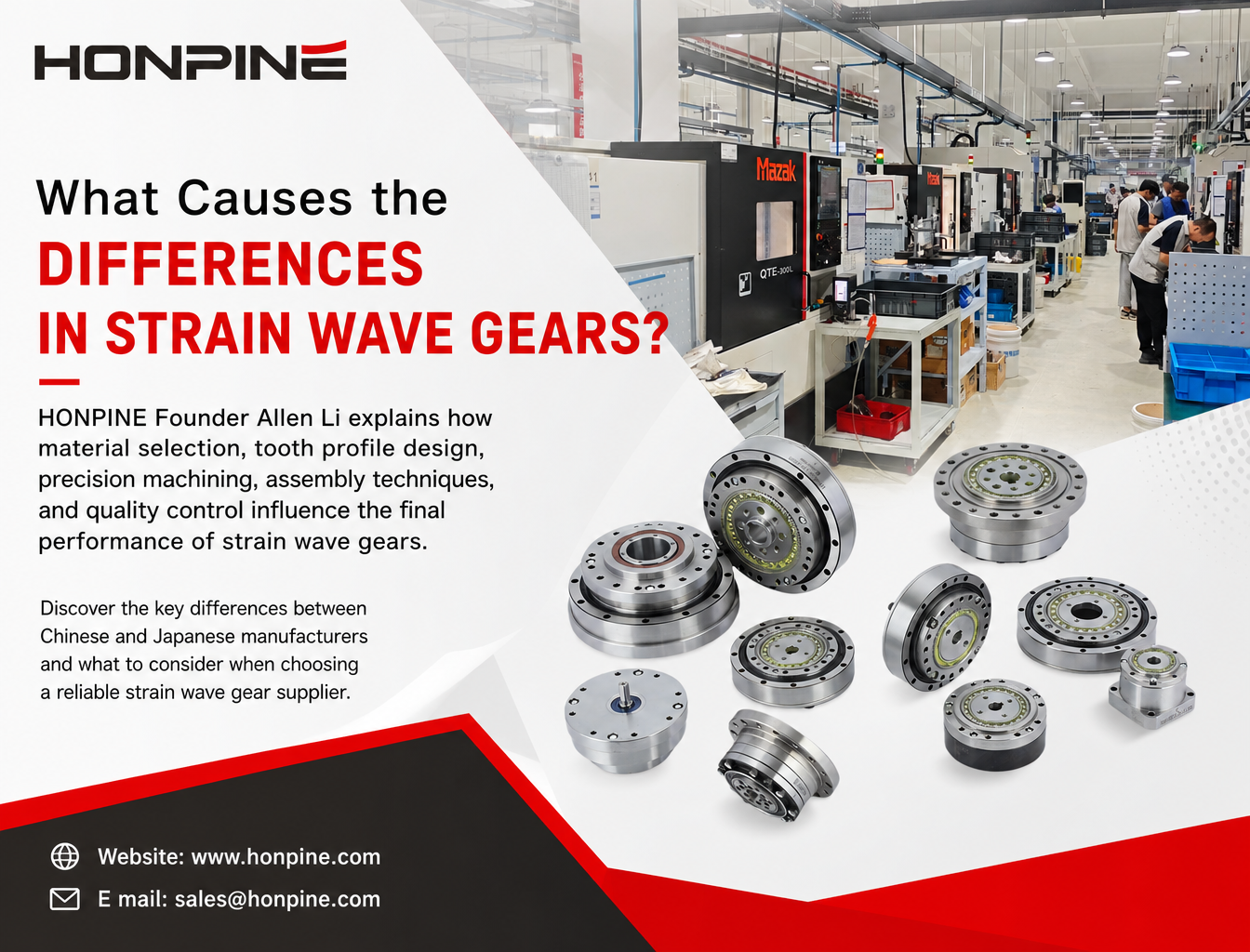
 Why Do Strain Wave Gear Manufacturers Produce Products with Such Different Levels of Quality and Precision?Strain wave gears share the same operating principle, but their quality, precision, and service life can vary significantly between manufacturers. What causes these differences? HONPINE Founder Allen Li explains how material selection, tooth profile design, precision machining, assembly techniques, and quality control influence the final performance of strain wave gears. Discover the key differences between Chinese and Japanese manufacturers and what to consider when choosing a reliable strain wave gear supplier.
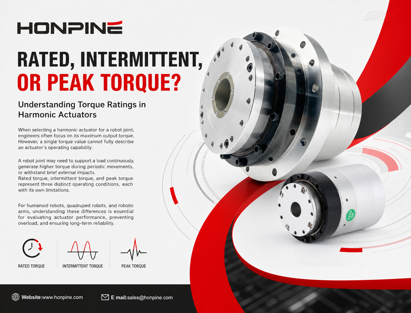
 What Are Rated, Intermittent, and Peak Torque in a Harmonic Actuator?When selecting a harmonic actuator for a robot joint, engineers often focus on its maximum output torque. However, a single torque value cannot fully describe an actuator's operating capability. A robot joint may need to support a load continuously, generate higher torque during periodic movements, or withstand brief external impacts. Rated torque, intermittent torque, and peak torque represent three distinct operating conditions, each with its own limitations. For humanoid robots, quadruped robots, and robotic arms, understanding these differences is essential for evaluating actuator performance, preventing overload, and ensuring long-term reliability.