







HONPINE HPJM Harmonic Joint Motor: Position Mode vs. Speed Mode – How to Choose the Right Control Mode?
Hello, I'm Theodore Li, Technical Director at HONPINE. When working with customers, one of the common questions I encounter concerns the difference between position mode and speed mode in harmonic joint motors.
Although both modes are widely used in robotic motion systems, they serve different control requirements. Choosing the wrong mode can affect motion accuracy, operating efficiency, and system safety.
In this article, I'll use the HONPINE HPJM harmonic joint motoras an example to explain how position mode and speed mode work, how they differ, and which applications are better suited to each mode.
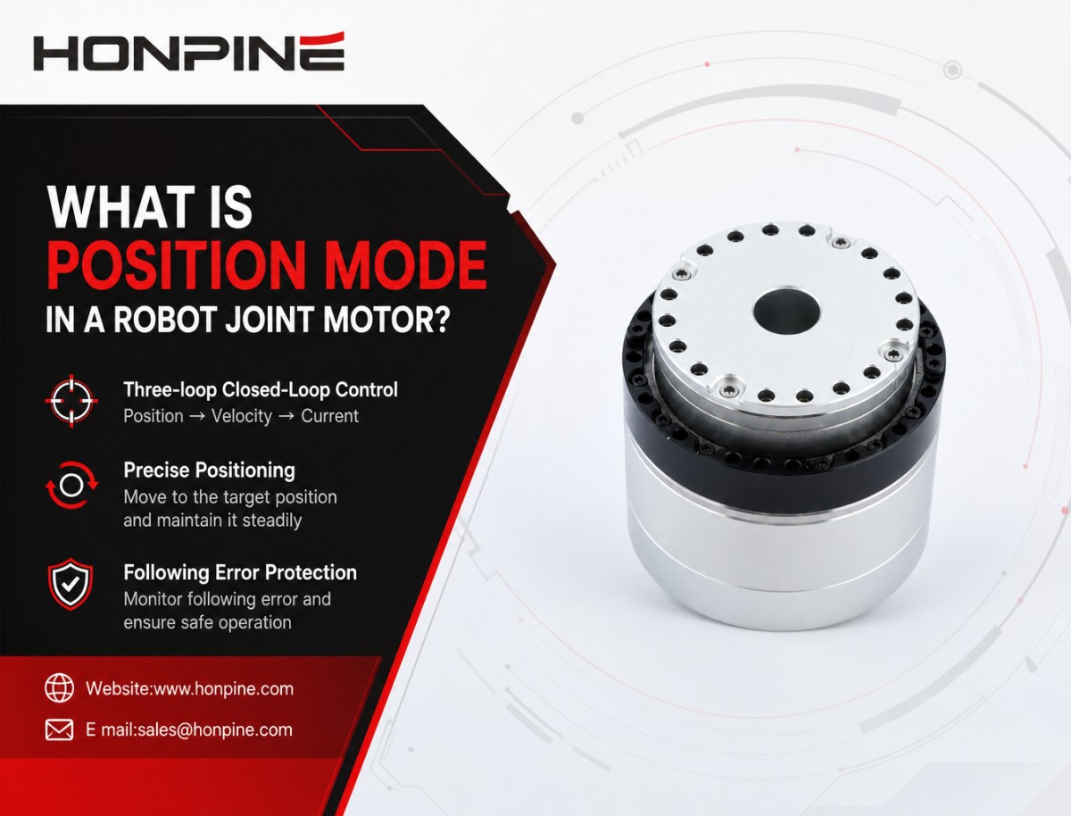
1. What Is Position Mode in a Robot Joint Motor?
Position mode controls the motor to move to a specified target position. It typically uses a three-loop closed-loop control architecture:
Position Loop → Velocity Loop → Current Loop
The outer position loop uses a PID controller to compare the target position with the actual position. The target position is usually expressed in encoder counts (cnt), which correspond to a specific angular position.
The position controller generates a velocity command for the inner velocity loop. The motor controller then manages acceleration and deceleration according to its configured motion profile, driving the joint toward the target angle.
Once the target position is reached, the controller maintains the commanded position through closed-loop control.
Following error monitoring: The controller monitors the difference between the target position and the actual position. If this following error exceeds the configured threshold, the motor can trigger fault code 0x8611 (Following Error) and stop operation, according to the drive's protection configuration.
This feature is particularly useful in applications where a joint must reach a defined angle and maintain its position.
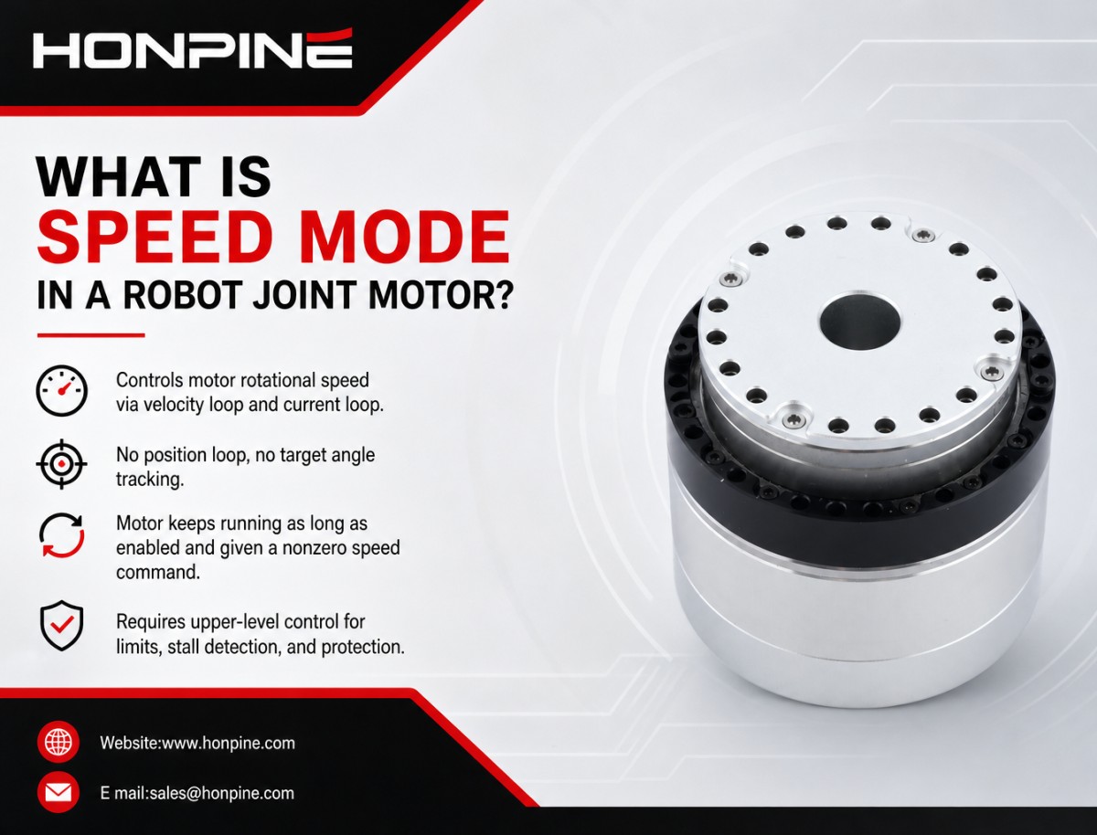
2. What Is Speed Mode in a Robot Joint Motor?
Speed mode directly controls the motor's rotational speed. It typically uses a two-loop closed-loop control architecture:
Velocity Loop → Current Loop
Unlike position mode, speed mode does not use an active position loop to command a target angle. Instead, the controller receives a target rotational speed, specified in 0.01 Hz units at the motor side.
The motor regulates its speed according to the given command and continues rotating as long as it remains enabled and receives a nonzero speed command.
In this mode:
The motor controls rotational speed rather than a target angular position.
It does not automatically stop when the joint reaches a particular angle.
It does not actively correct position following error through an outer position loop.
Following-error protection associated with position mode is therefore not available in the same way.
Important: Speed mode does not mean that the motor has no protection. However, if the mechanical load becomes jammed, the motor may continue producing torque according to its current limits and protection settings. The upper-level controller must implement appropriate current monitoring, stall detection, and travel-limit protection.
3. When Should You Use Position Mode?
Position mode is generally preferred when a robot joint needs to reach a specified angle, move between defined positions, or maintain a target posture.
Typical applications include humanoid robots, rehabilitation exoskeletons, collaborative robotic arms, pan-tilt systems, and oscillating mechanisms.
Humanoid Robot Joints: Hip, Knee, Ankle, Shoulder, and Elbow
Application requirements:
During walking, squatting, standing up, and other movements, each joint must move to a target angle and maintain the required posture.
Recommended mode: Position Mode
The upper-level motion planner calculates the target angle for each joint and converts it into the corresponding encoder count (cnt). These position commands are then sent to the HPJM motor.
The motor's internal three-loop control system manages the motion toward each target position, including acceleration, deceleration, and position holding.
This allows the main controller to focus on coordinating the robot's overall movement rather than implementing every joint's low-level position loop externally.
Protection considerations:
If a joint encounters mechanical jamming or excessive resistance, the following error may exceed its configured threshold, triggering a 0x8611 following-error fault and stopping the motor, provided that the relevant protection is enabled and configured correctly.
Tuning recommendations:
For high-load movements such as squatting and standing up, avoid setting the position-loop Kp gain excessively high, as this may cause vibration or oscillation.
A practical tuning sequence is to optimize the velocity-loop Kp and Ki gains first, followed by the position-loop gains. Position-loop Kd can then be adjusted where supported by the controller and required by the application.
Acceleration settings should also be appropriate for the joint's inertia. Excessive acceleration can increase following error and may trigger a fault, particularly when the joint carries a large inertial load.
Rehabilitation Exoskeleton Joints: Walking Assistance and Rehabilitation Training
Application requirements:
The exoskeleton needs to guide the user's limb to a specified joint angle, maintain a target posture, and respond safely when abnormal resistance occurs.
Recommended mode: Position Mode
The controller sets the target joint angle according to the rehabilitation program. The motor then drives the joint toward the specified position.
Safety considerations:
If the user resists the movement or the external load becomes excessive, the position following error may exceed its configured threshold and trigger a fault.
However, following-error protection alone is not sufficient for human-interactive safety. Rehabilitation exoskeletons should also incorporate appropriate torque or force limits, mechanical travel limits, emergency stops, and independent safety mechanisms.
Collaborative Robots and Small Robotic Arms
Application requirements:
The robot needs to move between defined positions, perform pick-and-place operations, and maintain a specified joint posture.
Recommended mode: Position Mode
The upper-level controller sends target positions to the joint motor. Multiple target positions can be configured to create simple point-to-point movements.
For example, during basic motor commissioning, a forward-and-reverse positioning test can be performed by repeatedly commanding different target positions.
Position mode is suitable for applications that require repeatable joint positioning and defined motion endpoints.
Pan-Tilt Systems and Oscillating Actuators
Application requirements:
The mechanism needs to rotate to a specified angle, stop, and remain at that position before moving again.
Recommended mode: Position Mode
The controller sends a target encoder count (cnt), and the motor moves to the corresponding angular position before maintaining it through closed-loop control.
Limitations of position mode:
Position mode is generally not the preferred choice for applications requiring continuous, unlimited rotation at a specified speed.
For motors with high reduction ratios, engineers must also pay attention to the conversion between encoder counts and actual output angle. For dual-encoder configurations, the motor-side and output-side encoder readings must be distinguished, and the applicable single-turn or multi-turn counting method must be confirmed.
4. When Should You Use Speed Mode?
Speed mode is generally preferred when a mechanism needs to rotate continuously at a specified speed, or when the upper-level controller is responsible for position and trajectory control.
In this configuration, the motor regulates its rotational speed, while the main controller processes external feedback and determines the required speed command.
Important safety consideration: Speed mode does not provide the same position following-error monitoring as position mode. If the mechanical system becomes jammed, the motor may continue producing torque within its configured limits. Therefore, the upper-level control system must implement appropriate travel limits, stall detection, and current-threshold monitoring.
Mobile Robot Drive Wheels
Application requirements:
A robot joint motor can also be used as a drive motor for a mobile robot wheel. The wheel needs to rotate at a specified speed to move the robot forward, backward, or around a turning path.
Recommended mode: Speed Mode
The main controller sends a target rotational speed to the motor, with the command expressed in 0.01 Hz units at the motor side.
The motor is responsible for maintaining the commanded speed, while the upper-level controller handles the robot's position and movement control.
For example, the main controller can use feedback from an IMU and wheel encoders or odometry to calculate the required wheel speeds and estimate the robot's movement.
Protection considerations:
If a wheel becomes blocked by an obstacle, speed mode will not automatically generate a position following-error fault. The motor may continue producing torque according to its current limits.
The upper-level controller should therefore monitor motor current and other relevant feedback signals. If the current exceeds a defined threshold or a stall condition is detected, the system should reduce or stop motor output according to its safety strategy.
Durability Testing and Continuous-Rotation Test Rigs
Application requirements:
The joint motor needs to rotate continuously at a constant speed during fatigue testing, endurance testing, or long-duration performance evaluation.
Recommended mode: Speed Mode
Set a fixed target speed and allow the motor to run continuously for the required test duration.
Speed mode is suitable for these applications because the primary requirement is stable rotational speed rather than movement to a specific target position.
Test systems should also include appropriate temperature monitoring, overload protection, and emergency stop functions.
5. Is Speed Mode Suitable for Force Control and Impedance Control?
Not necessarily.
The HONPINE HPJM motor supports current mode as well as position and speed control modes. For applications involving force control, torque control, or impedance control, current mode is generally a more appropriate starting point than speed mode.
In current mode, the controller directly regulates motor current. Since motor torque is related to motor current, this provides a basis for developing torque-related control strategies.
For impedance control and more advanced force-control applications, engineers may need additional feedback signals, such as output-side torque sensing, together with an external control algorithm.
Speed mode can still be used as part of certain control architectures, but it should not be treated as a direct substitute for current-based torque control.
6. Position Mode vs. Speed Mode: Key Differences
7. Conclusion: Choose the Control Mode According to Your Application
Position mode and speed mode are designed for different motion-control requirements. Neither is universally better than the other.
If a robot joint needs to reach a specific angle, perform point-to-point movements, or maintain a defined posture, position mode is generally the better choice.
If a motor needs to rotate continuously at a specified speed, while the upper-level controller manages the robot's position and movement, speed mode is usually more appropriate.
For force-control and impedance-control applications, current mode may provide a more suitable foundation.
When selecting a control mode for the HONPINE HPJM harmonic joint motor, engineers should consider the motion objective, mechanical load, control architecture, feedback configuration, and safety requirements together.
Contact HONPINE to learn more about HPJM harmonic joint motors, control modes, technical specifications, and integration solutions for robotic applications.

About Author
Theodore Li serves as the Technical Director at HONPINE, overseeing the R&D strategy for replication products, guiding team selection, and managing both pre-sales and after-sales operations.

Read More
Learn more about the story of HONPINE and industry trends related to precision transmission.
 What is robot joint actuator?How to Choose the Best Robot Rotary Joint Actuator?In core robot joint transmission solutions, planetary and harmonic rotary actuators each have their own strengths. Choosing the right type based on application requirements is essential to achieve the optimal balance between performance and cost.
 DD Motors VS Harmonic Rotary ActuatorsThis article provides an in-depth comparison between Direct Drive (DD) motors and harmonic rotary actuators, covering their transmission principles, advantages and disadvantages, and typical application fields.
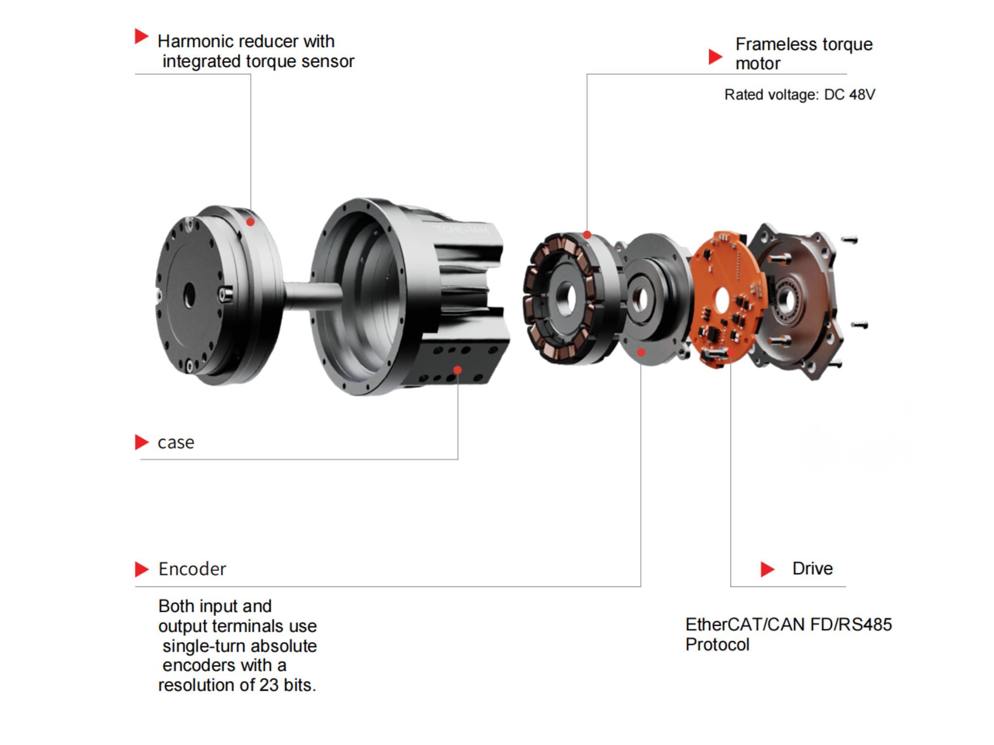
 OMG Ultra Compact Harmonic Drive Joint Module with Built-in Torque SensorHONPINE TCHL series harmonic drive joint module is a game-changing product that achieves disruptive improvements in multiple aspects such as lightweight design, integration level, and connection convenience. This article will analyze its revolutionary enhancements with you.
 The Role of Harmonic Drive Gears in Achieving 5–10 μm Accuracy in Dental Milling MachinesA dental milling machine is a CNC machining system used to directly process digital dental models into restorations such as crowns, bridges, veneers, inlays, and implant abutments. Dental milling machines require far higher operational accuracy and motion stability than ordinary equipment. This article explains how harmonic drive gear help dental milling machines achieve stable, continuous, and controllable operation.
 Why Are Harmonic Rotary Actuators Perfect for Medical Equipment?Harmonic rotary actuators (typically integrated systems consisting of a harmonic drive reducer, frameless torque motor, encoder, and optional brake) are regarded as key components in medical equipment. The core reason is that they simultaneously meet the most stringent medical requirements for precision, compact size, safety, and controllability. The following explanation is structured from three perspectives: technical characteristics, application scenarios, and medical value.
 High-Precision RV Reducers Perfectly Matched for Walking RobotsThe walking axis of a robot is a core component for power transmission and support. RV reducers provide extremely high rigidity, precision, and torque while maintaining a compact size and exceptional reliability, making them an ideal match for the demanding requirements of walking robot joints in terms of load capacity, impact resistance, and precision.
 How to Choose a High-Precision Rotary Actuator for Industrial Applications?Choosing the right precision rotary actuator requires more than checking rated torque. This guide explains how to calculate load torque, select the appropriate gear ratio, and evaluate structural configurations, mounting flanges, electromagnetic brakes, encoder resolution, and cable exit directions. Discover how HONPINE HAS, HAT, HAM, and HPG rotary actuator series meet different industrial motion control and precision positioning requirements.
 What Kind of Robot Joint Module Should You Choose for High-Precision Humanoid Robot Control?As humanoid robots move beyond basic walking and demonstration tasks toward complex real-world applications, their joint modules must deliver more than just high torque. Precise positioning, accurate torque control, structural stiffness, and dynamic response all play important roles in performing delicate operations. So, what kind of joint module should you choose for a humanoid robot designed to handle high-precision tasks? In this article, Theodore Li, Technical Director at HONPINE, introduces the HAG Harmonic Joint Module and explains five key features that make it suitable for demanding humanoid robot applications.
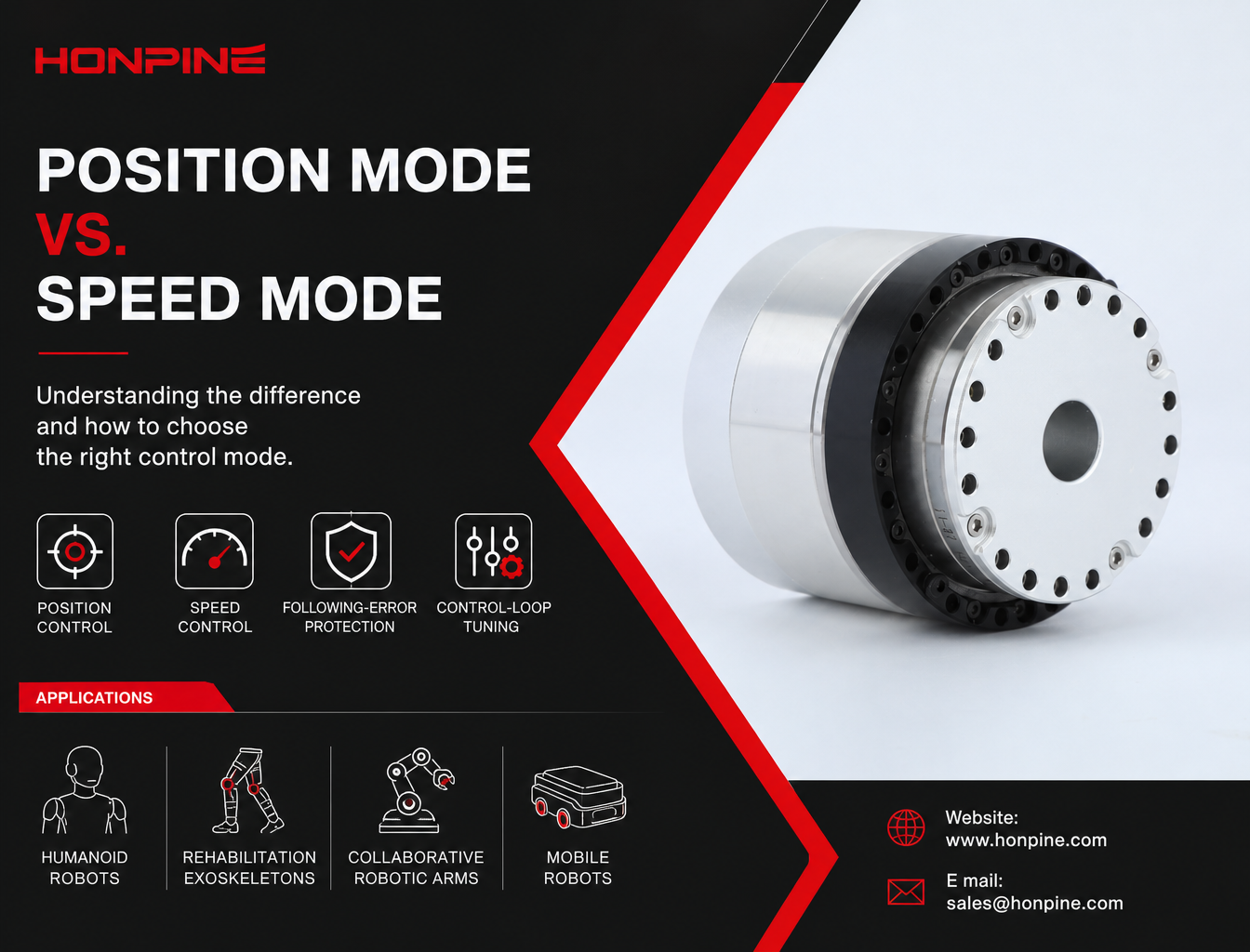
 HONPINE HPJM Harmonic Joint Motor: Position Mode vs. Speed Mode – How to Choose the Right Control Mode?Position mode and speed mode serve different motion-control requirements in robotic systems. Using the HONPINE HPJM harmonic joint motor as an example, this article explains their control architectures, operating principles, key differences, and application scenarios. From humanoid robot joints and rehabilitation exoskeletons to mobile robot drive wheels and continuous-rotation test systems, discover how to select the appropriate control mode based on motion objectives, mechanical loads, and system safety requirements.
 How Are Robot Industry Trends Shaping the Demand for Integrated Joint Modules and Hub Motors in 2026?The robotics industry is entering a new stage of development in 2026, with applications expanding from humanoid and quadruped robots to mobile manipulators, collaborative robots, and specialized robotic systems. As manufacturers move from prototype development toward commercialization and mass production, the demands on robotic drive systems are also changing. In this article, Allen Li, Founder of HONPINE, shares his observations on the evolving robotics market and explains why integrated joint modules and hub motors are becoming increasingly important for improving system integration, product consistency, and long-term operating reliability.
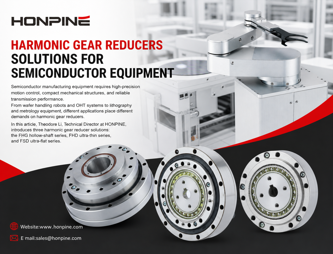
 3 Best Harmonic Gear Reducers for Semiconductor EquipmentSemiconductor manufacturing equipment requires high-precision motion control, compact mechanical structures, and reliable transmission performance. From wafer handling robots and OHT systems to lithography and metrology equipment, different applications place different demands on harmonic gear reducers. In this article, Theodore Li, Technical Director at HONPINE, introduces three harmonic gear reducer solutions: the FHG hollow-shaft series, FHD ultra-thin series, and FSD ultra-flat series. We will also examine 10 key technical parameters engineers should consider when selecting a harmonic gear reducer for semiconductor equipment, including rated torque, backlash, torsional rigidity, hollow shaft diameter, and permissible moment load.
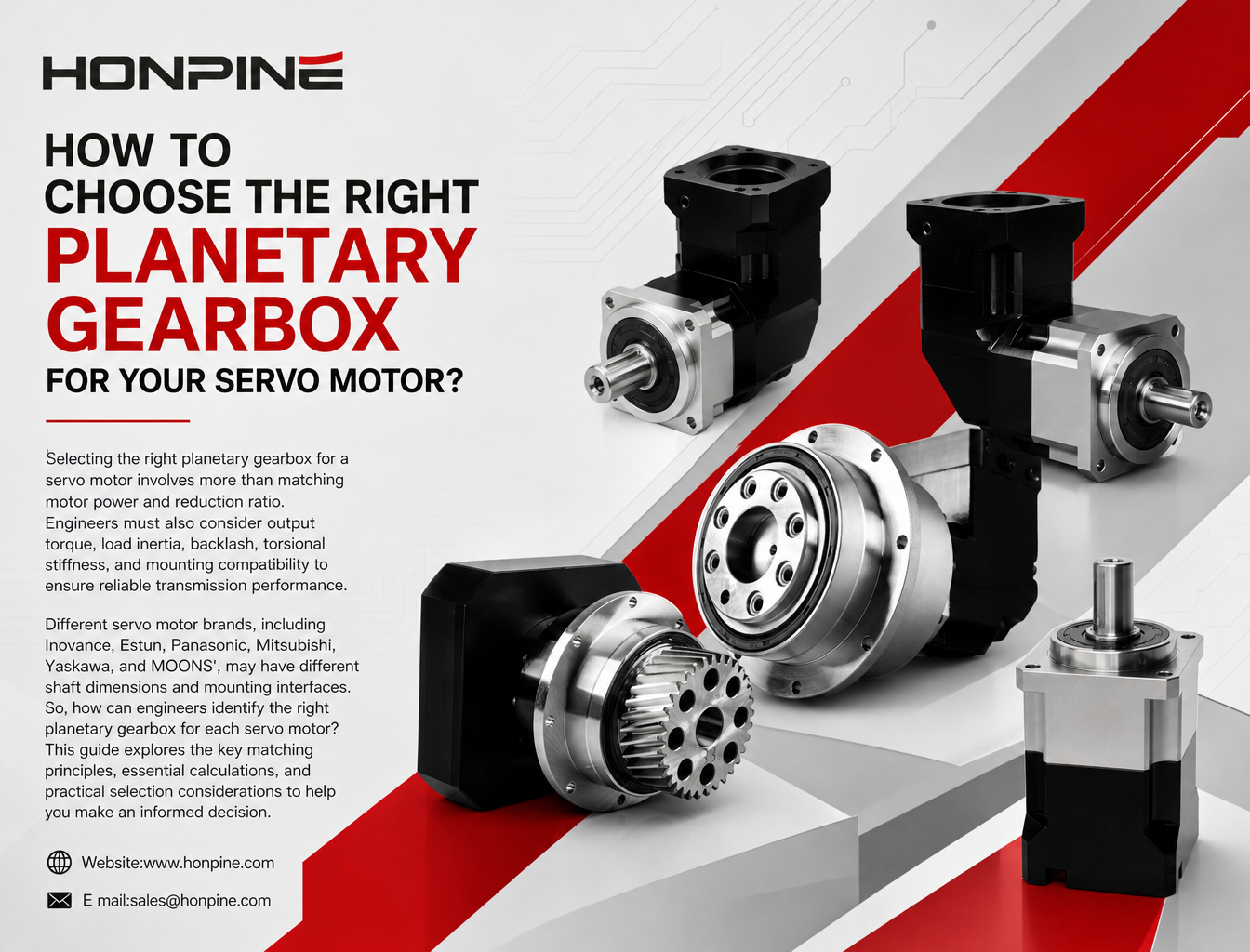
 How to Match Planetary Gearboxes with Servo Motors from 6 Major Brands?Selecting the right planetary gearbox for a servo motor involves more than matching motor power and reduction ratio. Engineers must also consider output torque, load inertia, backlash, torsional stiffness, and mounting compatibility to ensure reliable transmission performance. Different servo motor brands, including Inovance, Estun, Panasonic, Mitsubishi, Yaskawa, and MOONS', may have different shaft dimensions and mounting interfaces. So, how can engineers identify the right planetary gearbox for each servo motor? This guide explores the key matching principles, essential calculations, and practical selection considerations to help you make an informed decision.
Double Click
We provide harmonic drive reducer,planetary reducer,robot joint motor,robot rotary actuators,RV gear reducer,robot end effector,dexterous robot hand
 What is robot joint actuator?How to Choose the Best Robot Rotary Joint Actuator?In core robot joint transmission solutions, planetary and harmonic rotary actuators each have their own strengths. Choosing the right type based on application requirements is essential to achieve the optimal balance between performance and cost.
 DD Motors VS Harmonic Rotary ActuatorsThis article provides an in-depth comparison between Direct Drive (DD) motors and harmonic rotary actuators, covering their transmission principles, advantages and disadvantages, and typical application fields.
 OMG Ultra Compact Harmonic Drive Joint Module with Built-in Torque SensorHONPINE TCHL series harmonic drive joint module is a game-changing product that achieves disruptive improvements in multiple aspects such as lightweight design, integration level, and connection convenience. This article will analyze its revolutionary enhancements with you.
 How to Choose a High-Precision Rotary Actuator for Industrial Applications?Choosing the right precision rotary actuator requires more than checking rated torque. This guide explains how to calculate load torque, select the appropriate gear ratio, and evaluate structural configurations, mounting flanges, electromagnetic brakes, encoder resolution, and cable exit directions. Discover how HONPINE HAS, HAT, HAM, and HPG rotary actuator series meet different industrial motion control and precision positioning requirements.
 What Kind of Robot Joint Module Should You Choose for High-Precision Humanoid Robot Control?As humanoid robots move beyond basic walking and demonstration tasks toward complex real-world applications, their joint modules must deliver more than just high torque. Precise positioning, accurate torque control, structural stiffness, and dynamic response all play important roles in performing delicate operations. So, what kind of joint module should you choose for a humanoid robot designed to handle high-precision tasks? In this article, Theodore Li, Technical Director at HONPINE, introduces the HAG Harmonic Joint Module and explains five key features that make it suitable for demanding humanoid robot applications.
 HONPINE HPJM Harmonic Joint Motor: Position Mode vs. Speed Mode – How to Choose the Right Control Mode?Position mode and speed mode serve different motion-control requirements in robotic systems. Using the HONPINE HPJM harmonic joint motor as an example, this article explains their control architectures, operating principles, key differences, and application scenarios. From humanoid robot joints and rehabilitation exoskeletons to mobile robot drive wheels and continuous-rotation test systems, discover how to select the appropriate control mode based on motion objectives, mechanical loads, and system safety requirements.
 3 Best Harmonic Gear Reducers for Semiconductor EquipmentSemiconductor manufacturing equipment requires high-precision motion control, compact mechanical structures, and reliable transmission performance. From wafer handling robots and OHT systems to lithography and metrology equipment, different applications place different demands on harmonic gear reducers. In this article, Theodore Li, Technical Director at HONPINE, introduces three harmonic gear reducer solutions: the FHG hollow-shaft series, FHD ultra-thin series, and FSD ultra-flat series. We will also examine 10 key technical parameters engineers should consider when selecting a harmonic gear reducer for semiconductor equipment, including rated torque, backlash, torsional rigidity, hollow shaft diameter, and permissible moment load.
 How to Match Planetary Gearboxes with Servo Motors from 6 Major Brands?Selecting the right planetary gearbox for a servo motor involves more than matching motor power and reduction ratio. Engineers must also consider output torque, load inertia, backlash, torsional stiffness, and mounting compatibility to ensure reliable transmission performance. Different servo motor brands, including Inovance, Estun, Panasonic, Mitsubishi, Yaskawa, and MOONS', may have different shaft dimensions and mounting interfaces. So, how can engineers identify the right planetary gearbox for each servo motor? This guide explores the key matching principles, essential calculations, and practical selection considerations to help you make an informed decision.
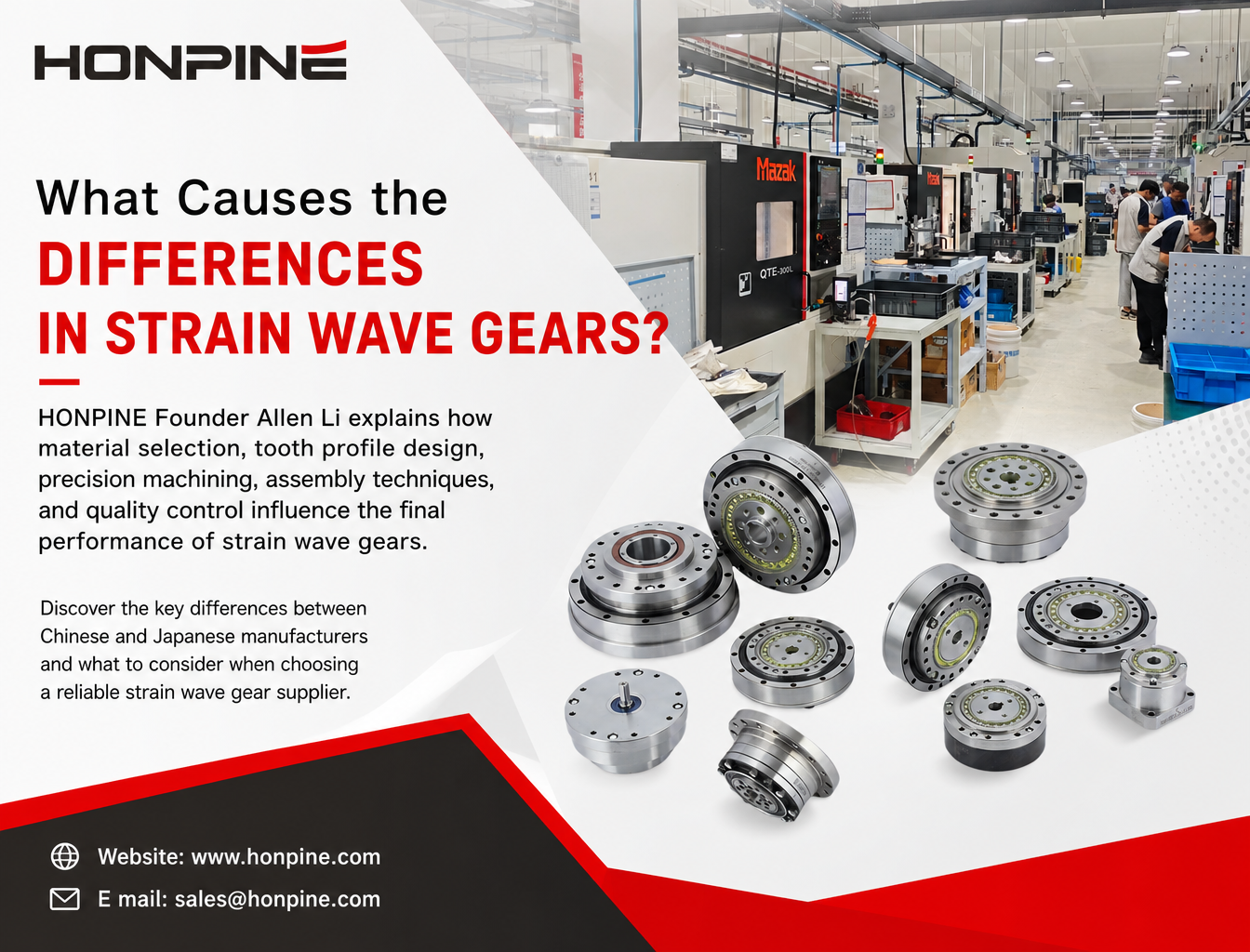
 Why Do Strain Wave Gear Manufacturers Produce Products with Such Different Levels of Quality and Precision?Strain wave gears share the same operating principle, but their quality, precision, and service life can vary significantly between manufacturers. What causes these differences? HONPINE Founder Allen Li explains how material selection, tooth profile design, precision machining, assembly techniques, and quality control influence the final performance of strain wave gears. Discover the key differences between Chinese and Japanese manufacturers and what to consider when choosing a reliable strain wave gear supplier.
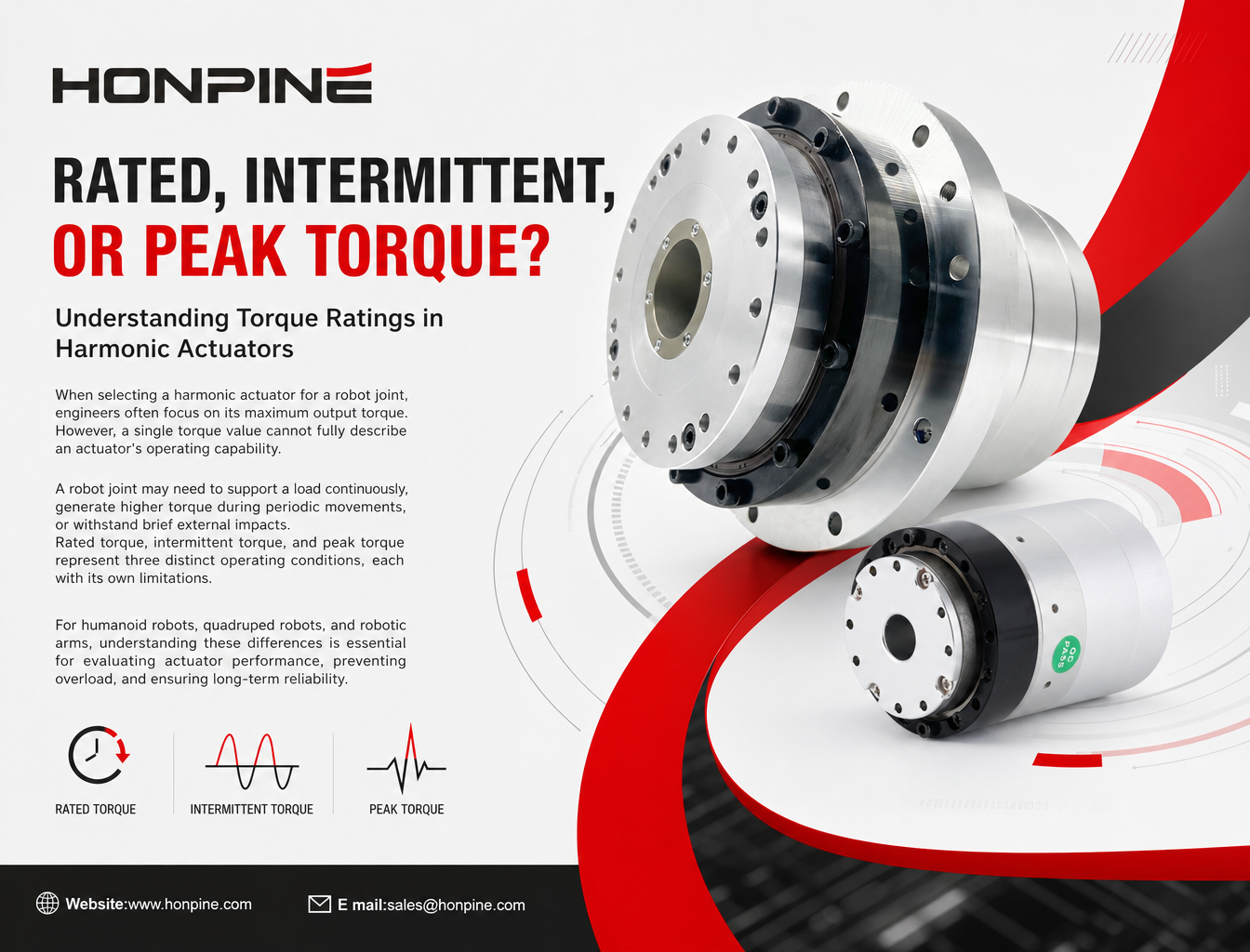
 What Are Rated, Intermittent, and Peak Torque in a Harmonic Actuator?When selecting a harmonic actuator for a robot joint, engineers often focus on its maximum output torque. However, a single torque value cannot fully describe an actuator's operating capability. A robot joint may need to support a load continuously, generate higher torque during periodic movements, or withstand brief external impacts. Rated torque, intermittent torque, and peak torque represent three distinct operating conditions, each with its own limitations. For humanoid robots, quadruped robots, and robotic arms, understanding these differences is essential for evaluating actuator performance, preventing overload, and ensuring long-term reliability.
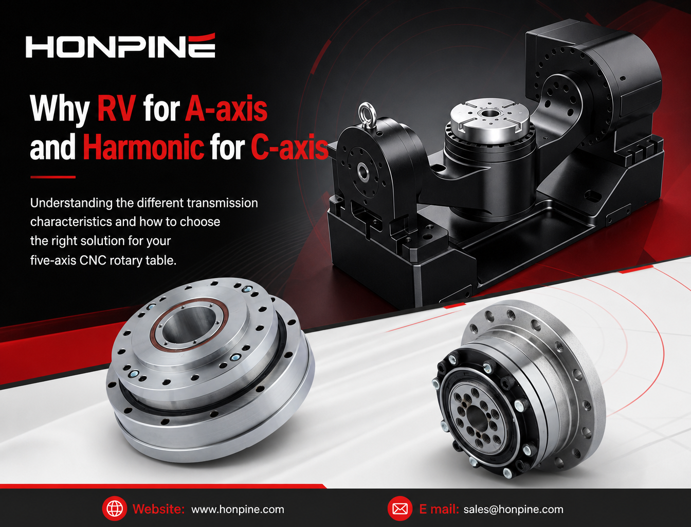
 Why Do Five-Axis CNC Rotary Tables Use Different Reducers for the A-Axis and C-Axis?Five-axis CNC rotary tables require different transmission characteristics for the A-axis and C-axis. While the A-axis often needs high torsional stiffness and load-bearing capacity to support the cradle assembly and workpiece, the C-axis places greater emphasis on low backlash, angular positioning accuracy, and dynamic response. This article explains why RV reducers are often considered for A-axis applications and harmonic reducers for C-axis applications, covering their working principles, mechanical advantages, output-side feedback, and key selection criteria for CNC machine tool manufacturers.
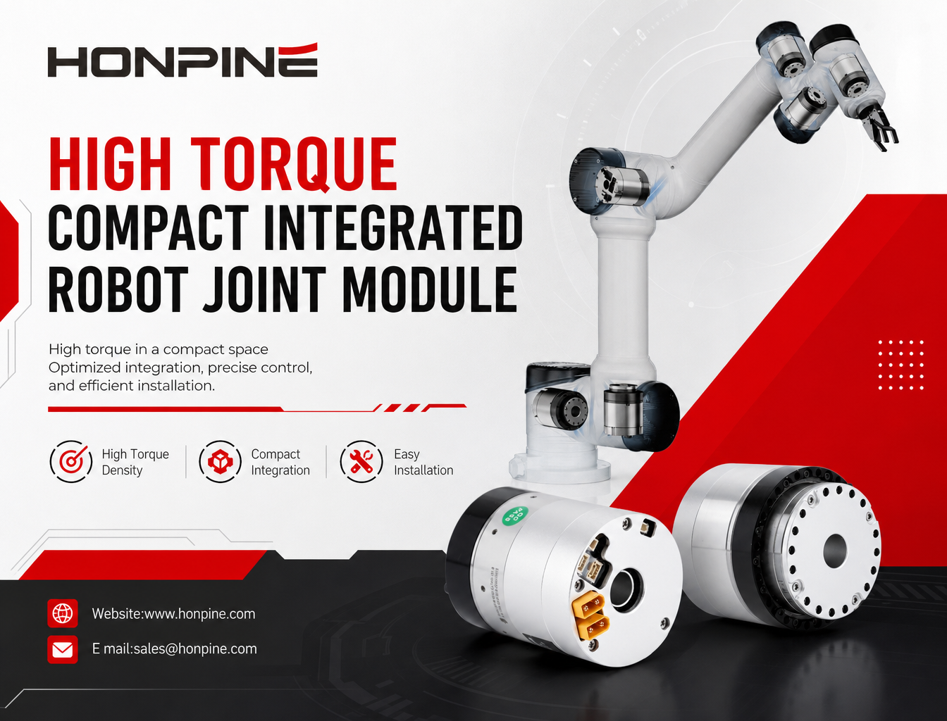
 How Does the HONPINE HPJM Integrated Robot Joint Module Deliver High Torque in a Compact Space?Learn how to optimize installation space while achieving high torque density in robotic joints. This article explores how the HONPINE HPJM integrated robot joint module uses integrated components, hollow-shaft cable routing, compact electrical connectors, and optimized mechanical mounting structures to reduce unnecessary space in humanoid robots and robotic arms.