








Why Do Industrial Robots and Heavy-Duty Equipment Prefer Dual-Disc RV Reducers?
Many engineers have the same question when they first encounter an RV reducer: if a single cycloidal disc can already achieve speed reduction, why are RV reducers used in industrial robots almost always designed with two cycloidal discs?
Adding a second disc means more components, more complicated assembly, and higher manufacturing costs. So what is the reason?
The answer can be summarized in one sentence: the second disc is not primarily there to provide reduction; it is there to improve accuracy, stability, load distribution, and service life.
In this article, we use our RV reducer assembly model and motion simulation to explain why the dual-disc configuration has become the mainstream architecture for industrial robots, machine tools, rotary tables, and other heavy-duty precision transmission systems.
Note: The numerical data and images in this article are based on simulation calculations and are provided for reference only.
How Does an RV Reducer Work?
An RV reducer, or cycloidal pinwheel reducer, has a relatively short transmission chain.
The input shaft drives an eccentric mechanism. The eccentric mechanism carries the cycloidal discs, which engage with the pins inside the pin housing. The resulting motion is then transmitted to the output through the output pin mechanism.
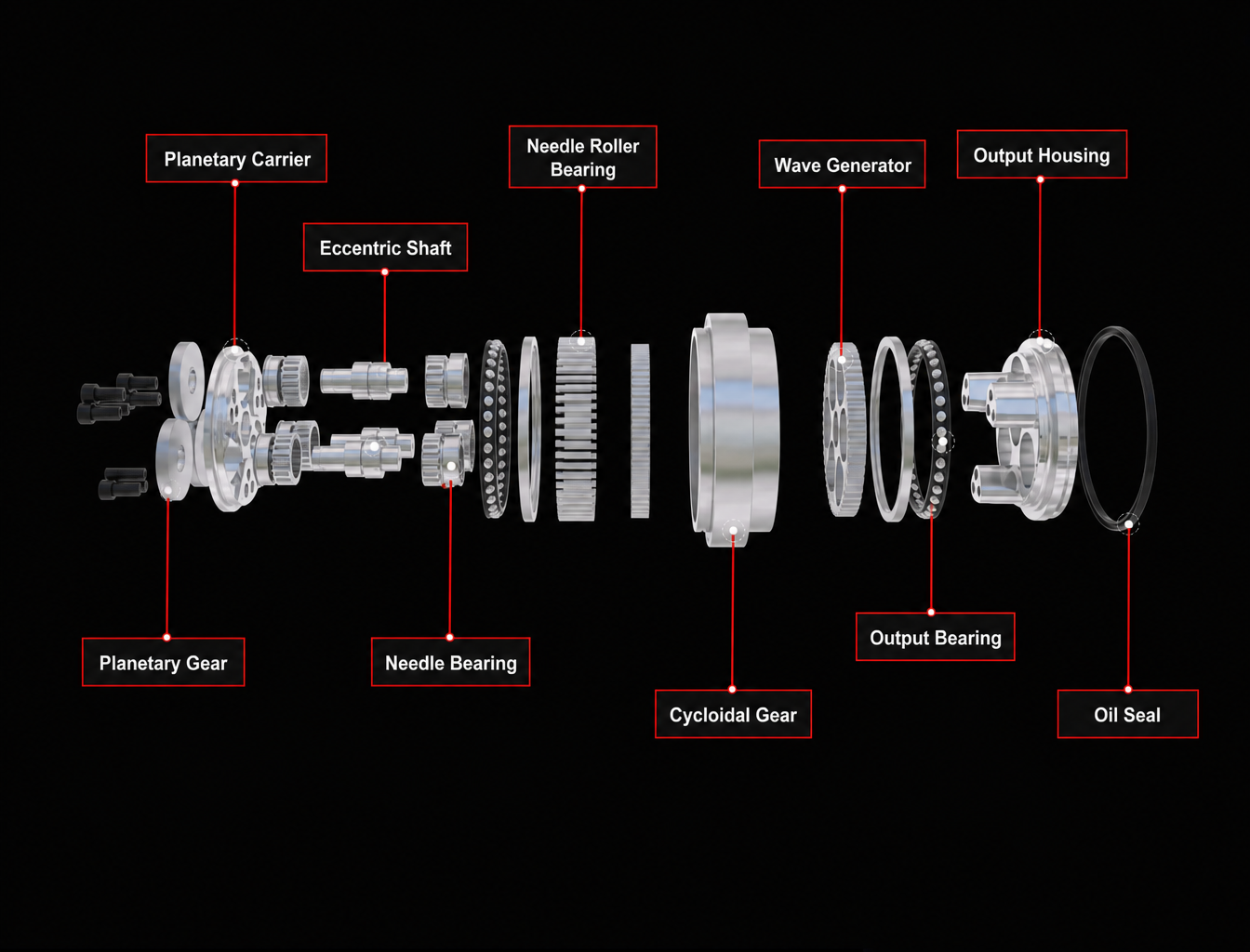
The following is an exploded view of our NX assembly model, including the pin housing with 40 pins, crankshaft, eccentric bearings, two cycloidal discs, and output disc. Each component in the model is generated directly from the engineering parameters of the transmission system.
The reduction principle can be summarized simply.
The pin housing has 40 pins, while the cycloidal disc has 39 teeth. During one revolution of the crankshaft, the cycloidal disc moves backward by one tooth position. Therefore, after 39 revolutions of the crankshaft, the output completes one revolution:
i = 39
The motion simulation provides a more intuitive way to understand this transmission process.
What Are the Problems With a Single-Disc RV Reducer?
Problem 1: Radial Force Imbalance
The cycloidal disc operates eccentrically. Its eccentric mass rotates around the center, while the meshing load is also concentrated within a particular sector.
In our numerical lever-method calculation, among the 40 pins, 19 pins meet the basic load-bearing conditions, while approximately 15 pins are actually loaded under the analyzed conditions.
The calculation shows that approximately 90% of the load is concentrated on 11 pins within a 90° sector, giving a load distribution coefficient of:
Kγ = 1.71
In a single-disc configuration, this concentrated load sector rotates together with the eccentric mass.
The result is increased vibration, noise, and bearing loading.
For heavy-duty equipment and industrial robot joints, these effects become increasingly important because the reducer must operate repeatedly under high torque and frequent acceleration and deceleration.
Advantages of a Dual-Disc RV Reducer
A dual-disc RV reducer places two identical cycloidal discs axially within the transmission.
Disc A operates on the +e eccentricity, while Disc B operates on the −e eccentricity. The two eccentric sections on the crankshaft are therefore positioned 180° apart.
However, simply installing two identical discs 180° apart is not enough.
Disc B must also be rotated by a specific phase angle:
Δφ = −180° / zc = −180° / 39 = −4.615°
This detail is particularly important during CAD modeling and assembly.
If an engineer simply duplicates the first cycloidal disc and installs the two discs with zero phase difference, the pin holes will not align correctly and the intended backlash-reduction effect cannot be achieved.
The left side of the comparison below shows the incorrect 0° phase arrangement, where the pin holes are visibly misaligned. The right side shows the correct −4.615° phase arrangement.
Benefit 1: Inertial Force Cancellation
Disc A operates at +e, while Disc B operates at −e.
The eccentric masses therefore move in opposite directions, allowing their first-order inertial forces to largely cancel each other.
This reduces vibration and helps the RV reducer operate more smoothly.
For industrial robot joints, this is one of the most direct benefits of the dual-disc architecture.
Lower vibration can also reduce dynamic loading on bearings and other transmission components.
Benefit 2: Backlash Can Be Reduced Through Preloading
To understand why the dual-disc structure can reduce backlash, we first need to understand where backlash comes from.
In our model, five major error sources were converted to the output angle using a lever-based calculation.
Under the example tolerance conditions, the output pin-hole clearance accounted for approximately 48% of the total calculated backlash, which was roughly equivalent to the combined contribution of the other four sources.
The cycloidal tooth profile itself accounted for only about one quarter of the total.
This means that a major part of the backlash comes from the clearance chain, rather than simply from the cycloidal tooth profile.
The phase difference between the two cycloidal discs provides a way to compensate for part of this clearance.
By adjusting the phase, one disc can be positioned against one side of the clearance while the other disc contacts the opposite side.
The principle is similar to the anti-backlash mechanism of a preloaded double-nut ball screw.
However, there is an important engineering window that is often overlooked.
Our calculation gives an assembly phase window of approximately:
ε* = 79″
When the phase error remains within this window, the backlash-reduction effect remains effective.
Once the phase error exceeds the allowable window, the two discs can begin to oppose each other and partially lock up. Backlash may continue to decrease, but friction and temperature rise at the same time.
Therefore, dual-disc RV reducer acceptance should evaluate both backlash and no-load torque.
Looking at only one of these parameters can give a misleading impression of the actual assembly quality.
Benefit 3: Load Sharing
The two cycloidal discs provide parallel load paths.
In an ideal theoretical condition, each disc would carry approximately 50% of the transmission load.
In an actual reducer, manufacturing tolerances and phase errors mean that the load is not perfectly divided.
Nevertheless, the dual-disc configuration significantly reduces load concentration.
More teeth can participate in load transmission, which can reduce contact stress and improve wear distribution.
This load-sharing characteristic is particularly valuable in high-torque and long-service applications.
Benefit 4: Higher Torsional Stiffness
The dual-disc configuration creates an additional parallel transmission path.
This can increase the effective torsional stiffness of the transmission system and reduce output-end angular movement under load.
For applications such as welding robots, material-handling robots, industrial rotary tables, and machine tools, torsional stiffness is particularly important because the output must maintain its position under changing external loads.
Single-Disc vs. Dual-Disc RV Reducer
The additional cycloidal disc increases component count and assembly complexity, but it also provides improvements in force balance, load sharing, backlash control, and torsional stiffness.
Where Are Dual-Disc RV Reducers Used?
Dual-disc RV reducers are widely associated with applications that require high torque, high stiffness, accurate positioning, and long-term reliability.
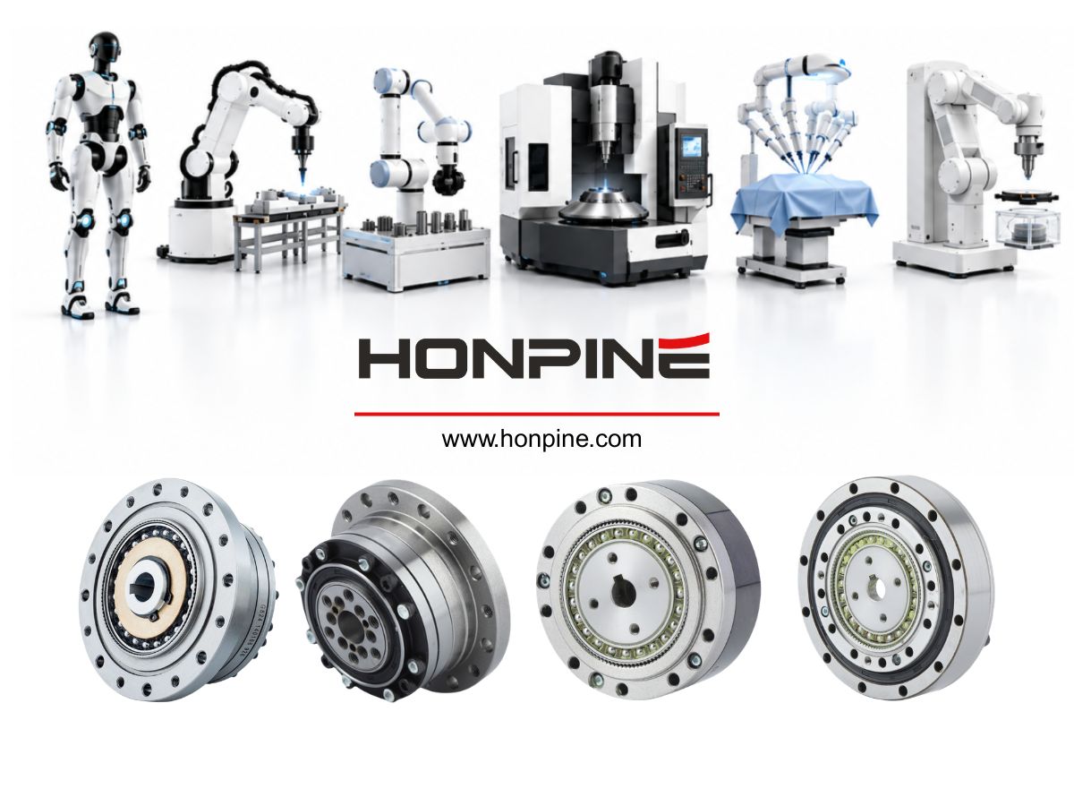
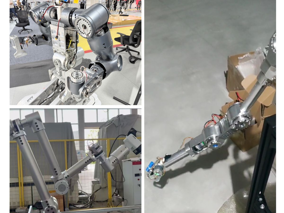
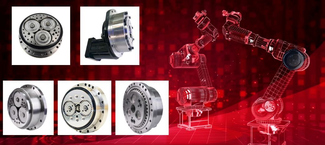
HONPINE RV reducers are currently used in applications including heavy-duty robotic arms, industrial positioners, industrial rotary tables, and machine-tool systems.
RV Reducers for Industrial Robots
Industrial robot joints do not primarily prioritize saving the cost of one cycloidal disc.
They require a combination of:
High positioning accuracy
High torsional stiffness
Low backlash
High load capacity
Long service life
Stable operation
High reliability
The dual-disc RV architecture adds manufacturing and assembly complexity, but provides benefits in backlash reduction, vibration control, load sharing, and stiffness.
For this reason, dual-cycloidal-disc RV reducers with phase preloading are widely used in industrial robot joints.
Single-disc RV configurations are more commonly found in teaching systems, experimental equipment, or cost-sensitive applications where the requirements for stiffness, vibration, and long-term heavy-duty operation are lower.
RV Reducers for Industrial Positioners
Industrial positioners share an important characteristic with robot joints: they often handle large loads while the output shaft is also exposed to eccentric loads and overturning moments.
A welding positioner, for example, needs to rotate a workpiece while maintaining stable positioning.
If the reducer has excessive backlash or insufficient torsional stiffness, the output can experience small angular movements during acceleration, deceleration, direction reversal, or external loading from the welding process.
Industrial positioners therefore pay close attention to:
Output torque
Torsional stiffness
Backlash
Allowable overturning moment
High-frequency start-stop operation
Long-term operating life
These are also areas where the dual-disc RV architecture can provide important mechanical advantages.
RV Reducers for Industrial Rotary Tables
Heavy-duty industrial rotary tables, robotic rotary tables, welding tables, and precision positioning tables place similar demands on the transmission system.
The requirement is not simply to make the table rotate.
The system must accurately rotate a large load to the target position and maintain stable positioning after the motion stops.
For this reason, important parameters for an RV reducer used in a rotary table include:
Backlash
Torsional stiffness
Axial and radial load capacity
Allowable overturning moment
Output torque
Positioning accuracy
Long-term operating reliability
A dual-disc RV reducer can therefore be particularly suitable for rotary applications where high load and stable positioning are required.
Why Is the Dual-Disc Configuration the Mainstream RV Architecture?
The reduction function of an RV reducer comes from the cycloidal pin-tooth transmission.
The additional cycloidal disc does not fundamentally create the reduction ratio.
Its primary value lies in improving the mechanical behavior of the transmission system.
The single-disc structure addresses the basic question:
Can the mechanism achieve speed reduction?
The dual-disc structure addresses more demanding questions:
Can it reduce vibration, distribute load, control backlash, increase stiffness, and operate reliably over a long service life?
This distinction explains why dual-disc RV reducers are widely used in industrial robots, machine tools, heavy-duty rotary tables, and other precision transmission applications.
The small −4.615° phase difference in this example is therefore much more than a CAD assembly detail. It is one of the key factors that turns two cycloidal discs into a coordinated precision transmission system.
Read More
Learn more about the story of HONPINE and industry trends related to precision transmission.
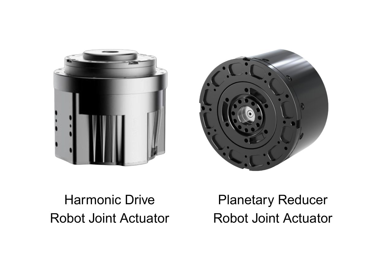
 What is robot joint actuator?How to Choose the Best Robot Rotary Joint Actuator?In core robot joint transmission solutions, planetary and harmonic rotary actuators each have their own strengths. Choosing the right type based on application requirements is essential to achieve the optimal balance between performance and cost.
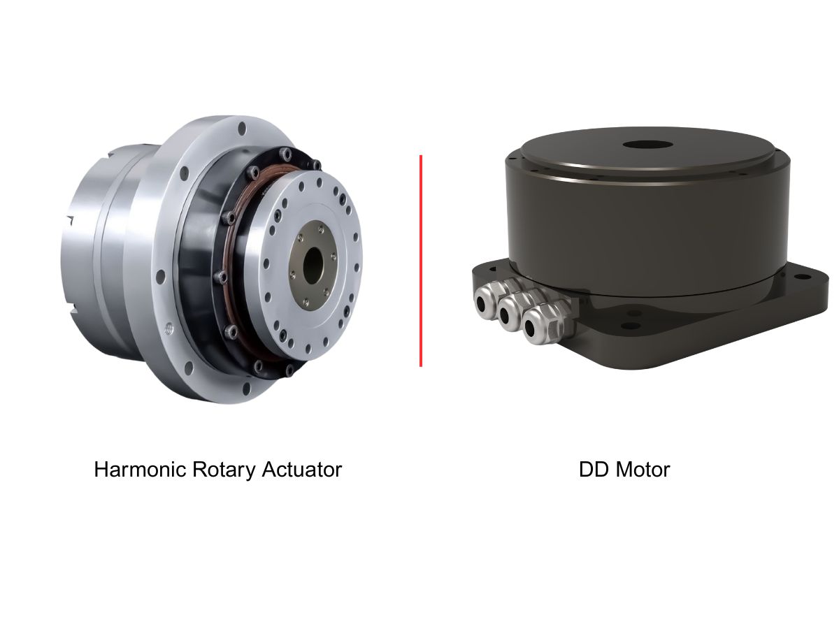
 DD Motors VS Harmonic Rotary ActuatorsThis article provides an in-depth comparison between Direct Drive (DD) motors and harmonic rotary actuators, covering their transmission principles, advantages and disadvantages, and typical application fields.
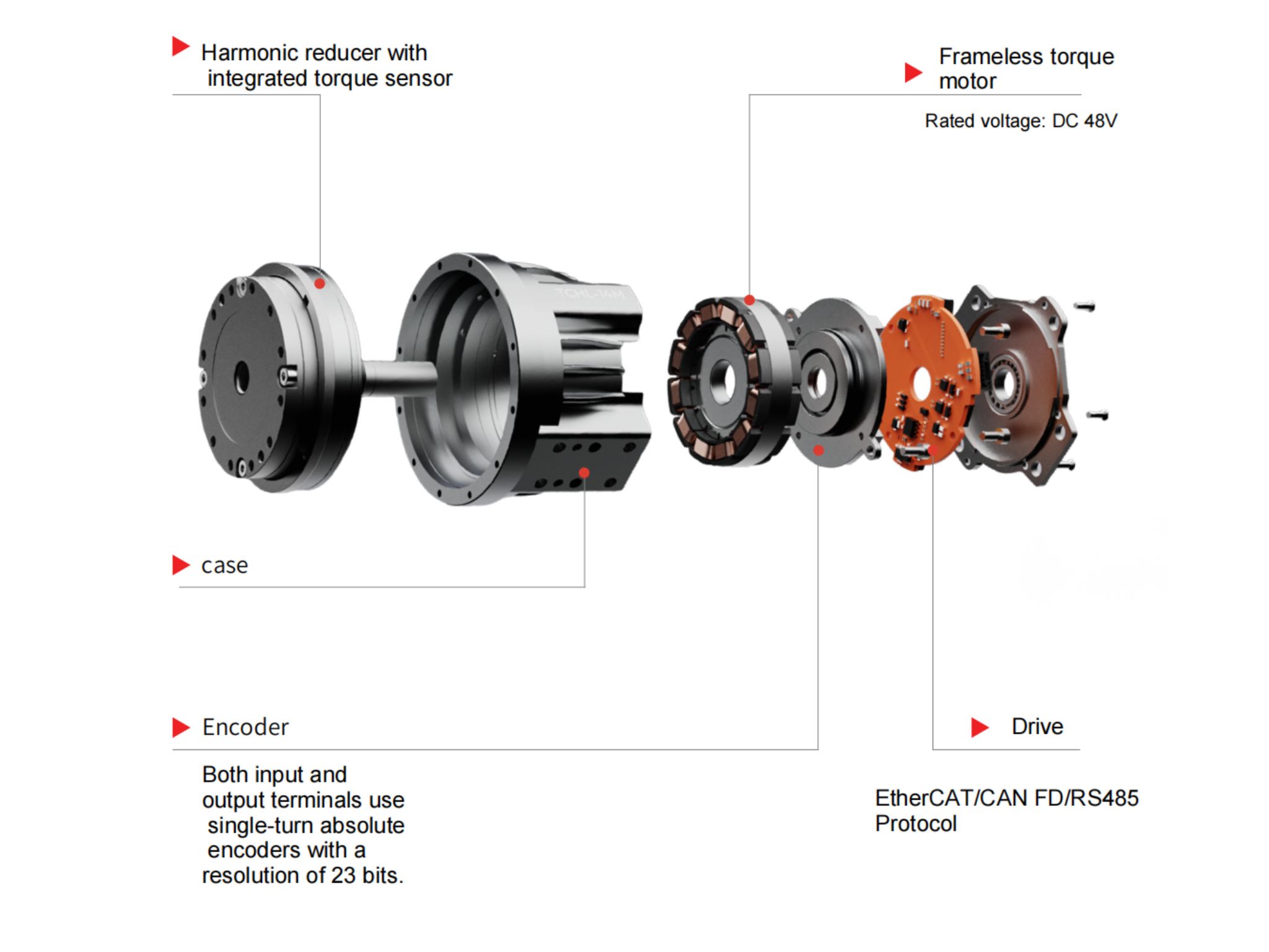
 OMG Ultra Compact Harmonic Drive Joint Module with Built-in Torque SensorHONPINE TCHL series harmonic drive joint module is a game-changing product that achieves disruptive improvements in multiple aspects such as lightweight design, integration level, and connection convenience. This article will analyze its revolutionary enhancements with you.
 The Role of Harmonic Drive Gears in Achieving 5–10 μm Accuracy in Dental Milling MachinesA dental milling machine is a CNC machining system used to directly process digital dental models into restorations such as crowns, bridges, veneers, inlays, and implant abutments. Dental milling machines require far higher operational accuracy and motion stability than ordinary equipment. This article explains how harmonic drive gear help dental milling machines achieve stable, continuous, and controllable operation.
 Why Are Harmonic Rotary Actuators Perfect for Medical Equipment?Harmonic rotary actuators (typically integrated systems consisting of a harmonic drive reducer, frameless torque motor, encoder, and optional brake) are regarded as key components in medical equipment. The core reason is that they simultaneously meet the most stringent medical requirements for precision, compact size, safety, and controllability. The following explanation is structured from three perspectives: technical characteristics, application scenarios, and medical value.
 High-Precision RV Reducers Perfectly Matched for Walking RobotsThe walking axis of a robot is a core component for power transmission and support. RV reducers provide extremely high rigidity, precision, and torque while maintaining a compact size and exceptional reliability, making them an ideal match for the demanding requirements of walking robot joints in terms of load capacity, impact resistance, and precision.
 Hollow Robot Joint Module: Why Cable Routing Matters in Robotic Joints?A hollow robot joint module provides an internal passage for power cables, signal lines, pneumatic tubes, and other end-effector connections. Compared with external cable routing, a hollow joint module can help reduce cable exposure, improve system integration, and create a cleaner motion path for robotic arms. This article explains why internal cable routing matters in robotic joints and what to consider when selecting a hollow joint module for robotic applications.
 Robot Joint Actuator Selection: From Inertia Matching to System-Level OptimizationSelecting a robot joint actuator is not simply a matter of matching motor torque or achieving a suitable inertia ratio. In a real robotic system, reduction ratio, load spectrum, thermal performance, mechanical stiffness, transmission nonlinearity, encoder architecture, control bandwidth, and service life all interact to determine the final result. A joint may meet its peak torque requirement and still experience vibration, overheating, positioning errors, or premature wear in real operation. This article examines the engineering logic behind robot joint actuator selection and explains why moving from single-parameter matching to system-level optimization can lead to more reliable and predictable robotic joint performance.
 HONPINE HAG Robot Joint Module Undergoing Pre-Shipment InspectionThe HONPINE HAG Robot Joint Module is currently undergoing pre-shipment inspection before delivery.
 How to Choose a Small Harmonic Actuator?HONPINE Series 11 small harmonic actuators provide a compact, high-performance rotary motion solution for precision automation applications. Available with hollow or solid shafts, 48V or 220V options, optional brakes, absolute encoders, and different reduction ratios, the Series 11 is designed for applications requiring compact dimensions, controlled torque, and precise positioning.
 How to Choose a Wheel Motor for a Heavy-Duty AGV? Key Challenges from Dynamic Loads to 120-Ton AGV Drive Wheel SystemsSelecting a Heavy-Duty AGV Wheel Motor is more than matching motor power or rated torque to the vehicle's payload. As AGVs move from conventional material handling to multi-ton and even 120-ton-class applications, the drive wheel system must handle dynamic loads, acceleration, braking, turning forces, traction, and long-term mechanical stress. The actual challenge lies in matching wheel load capacity, wheel-end torque, gearbox performance, steering architecture, suspension, and chassis design under real operating conditions. This article examines the key challenges of Heavy-Duty AGV Wheel Motor selection and explains how Steering Drive Wheels and Differential Drive Wheels can be evaluated for different heavy-duty AGV applications.
 DD Motor Servo System: How to Understand Mechanical Resonance and Solve Machine Vibration?This article explains the relationship between DD motor servo tuning, mechanical resonance, and servo bandwidth in direct drive motion systems. It examines why vibration and instability can occur even after repeated servo parameter adjustments, and explains how mechanical stiffness, moving mass, bearing conditions, load distribution, and structural geometry affect resonance frequency. The article also compares approaches for high- and low-frequency resonance, explains when digital notch filtering can be effective, and provides a practical tuning strategy for engineers working with DD motors, direct drive torque motors, and linear motors.
Double Click
We provide harmonic drive reducer,planetary reducer,robot joint motor,robot rotary actuators,RV gear reducer,robot end effector,dexterous robot hand
 What is robot joint actuator?How to Choose the Best Robot Rotary Joint Actuator?In core robot joint transmission solutions, planetary and harmonic rotary actuators each have their own strengths. Choosing the right type based on application requirements is essential to achieve the optimal balance between performance and cost.
 DD Motors VS Harmonic Rotary ActuatorsThis article provides an in-depth comparison between Direct Drive (DD) motors and harmonic rotary actuators, covering their transmission principles, advantages and disadvantages, and typical application fields.
 OMG Ultra Compact Harmonic Drive Joint Module with Built-in Torque SensorHONPINE TCHL series harmonic drive joint module is a game-changing product that achieves disruptive improvements in multiple aspects such as lightweight design, integration level, and connection convenience. This article will analyze its revolutionary enhancements with you.
 Hollow Robot Joint Module: Why Cable Routing Matters in Robotic Joints?A hollow robot joint module provides an internal passage for power cables, signal lines, pneumatic tubes, and other end-effector connections. Compared with external cable routing, a hollow joint module can help reduce cable exposure, improve system integration, and create a cleaner motion path for robotic arms. This article explains why internal cable routing matters in robotic joints and what to consider when selecting a hollow joint module for robotic applications.
 Robot Joint Actuator Selection: From Inertia Matching to System-Level OptimizationSelecting a robot joint actuator is not simply a matter of matching motor torque or achieving a suitable inertia ratio. In a real robotic system, reduction ratio, load spectrum, thermal performance, mechanical stiffness, transmission nonlinearity, encoder architecture, control bandwidth, and service life all interact to determine the final result. A joint may meet its peak torque requirement and still experience vibration, overheating, positioning errors, or premature wear in real operation. This article examines the engineering logic behind robot joint actuator selection and explains why moving from single-parameter matching to system-level optimization can lead to more reliable and predictable robotic joint performance.
 How to Choose a Small Harmonic Actuator?HONPINE Series 11 small harmonic actuators provide a compact, high-performance rotary motion solution for precision automation applications. Available with hollow or solid shafts, 48V or 220V options, optional brakes, absolute encoders, and different reduction ratios, the Series 11 is designed for applications requiring compact dimensions, controlled torque, and precise positioning.
 How to Choose a Wheel Motor for a Heavy-Duty AGV? Key Challenges from Dynamic Loads to 120-Ton AGV Drive Wheel SystemsSelecting a Heavy-Duty AGV Wheel Motor is more than matching motor power or rated torque to the vehicle's payload. As AGVs move from conventional material handling to multi-ton and even 120-ton-class applications, the drive wheel system must handle dynamic loads, acceleration, braking, turning forces, traction, and long-term mechanical stress. The actual challenge lies in matching wheel load capacity, wheel-end torque, gearbox performance, steering architecture, suspension, and chassis design under real operating conditions. This article examines the key challenges of Heavy-Duty AGV Wheel Motor selection and explains how Steering Drive Wheels and Differential Drive Wheels can be evaluated for different heavy-duty AGV applications.
 DD Motor Servo System: How to Understand Mechanical Resonance and Solve Machine Vibration?This article explains the relationship between DD motor servo tuning, mechanical resonance, and servo bandwidth in direct drive motion systems. It examines why vibration and instability can occur even after repeated servo parameter adjustments, and explains how mechanical stiffness, moving mass, bearing conditions, load distribution, and structural geometry affect resonance frequency. The article also compares approaches for high- and low-frequency resonance, explains when digital notch filtering can be effective, and provides a practical tuning strategy for engineers working with DD motors, direct drive torque motors, and linear motors.
 Why Do Industrial Robots and Heavy-Duty Equipment Prefer Dual-Disc RV Reducers?Many engineers have the same question when they first look inside an RV reducer: if a single cycloidal disc can already achieve speed reduction, why do industrial robot RV reducers almost always use two discs? The additional disc increases the number of components, assembly complexity, and manufacturing cost, so its purpose deserves a closer look. The answer is not simply a higher reduction ratio. A dual-disc RV reducer is designed to improve the overall mechanical behavior of the transmission through better force balance, load sharing, backlash control, torsional stiffness, and long-term reliability. In this article, we use an RV reducer assembly model and motion simulation to examine these mechanisms and explain why the dual-disc architecture is widely used in industrial robots, machine tools, rotary tables, and other heavy-duty precision transmission systems.
 Small Size Harmonic Drive Reducer: Advantages, Applications and Selection GuideSmall size harmonic drive reducer for compact precision motion systems, offering high reduction ratio, near-zero backlash, low weight and accurate transmission.
 High Precision Harmonic Drive Robot Joint Actuator Solution for Robotic ElbowsThe robotic elbow joint plays a critical role in arm flexion, posture adjustment, and end-effector positioning. As humanoid robots, collaborative robots, and robotic arms become more capable, elbow actuators need to deliver high torque and precise motion within increasingly limited installation spaces. A high precision harmonic drive robot joint actuator integrates the harmonic reducer, motor, encoder, brake, and drive system into a compact unit, providing low backlash, high stiffness, high torque density, and accurate motion control. In this article, HONPINE introduces three joint actuator series suitable for robotic elbow applications, covering different requirements for size, torque, speed, precision, and integration.
 Explosion-Proof Robot Joint Solution for Chemical Inspection Quadruped Robots: Planetary Joint Actuator with Up to 500 N·m Peak TorqueIn petrochemical, mining, power, and other hazardous environments, inspection robots are moving beyond simple monitoring toward practical operations such as tool handling, equipment inspection, and emergency response. This shift places higher demands on robot joint actuators, particularly in explosion protection, torque output, thermal management, environmental resistance, and mobility. HONPINE's explosion-proof robot joint actuator is designed for quadruped inspection robots and other hazardous-environment robotic platforms, integrating high-load planetary transmission with explosion-proof design and reliable motion performance. With up to 500 N·m peak torque per joint, optional IP67 protection, and Ex db IIB T4 Gb certification, the solution is designed to support demanding robotic applications in high-risk industrial environments.