







The Complete Harmonic Joint Actuator Solution for Humanoid Robots: HPJM Series Selection Guide
Humanoid robots require a carefully coordinated joint drive system to balance payload capacity, motion speed, positioning accuracy, dynamic response, and overall weight. Selecting the right harmonic joint actuator for each joint is essential to achieving stable walking, precise manipulation, and reliable long-term operation.
Hello, I’m Theodore Li, Technical Director at HONPINE. In previous articles, I have discussed harmonic joint actuator solutions for individual humanoid robot joints, including the shoulders, waist, arms, and legs. Following those articles, several readers on LinkedIn asked for a more comprehensive solution covering the entire humanoid robot.
In this guide, I will explain how to configure a complete humanoid robot joint drive system using actual models from the HONPINE HPJM harmonic joint actuator series. The recommendations cover joint positioning, torque requirements, reduction ratios, dynamic performance, and brake configurations to help engineers develop a practical starting point for whole-body joint selection.
The final configuration should always be validated against the robot’s weight, payload, joint geometry, required motion profiles, thermal limits, and safety requirements.
1. Fundamental Selection Principles for a Humanoid Robot Harmonic Joint Actuator System
Before selecting individual HPJM models, engineers should understand four fundamental principles that influence the performance of the entire robot.
1.1 Lightweight Distal Joints and High-Torque Proximal Joints
The wrist and ankle are located relatively far from the robot’s main structural support. Their mass and rotational inertia can significantly affect dynamic response and control performance. Lightweight, compact harmonic joint actuators are therefore preferred where their torque capacity is sufficient.
By contrast, the shoulder, hip, and knee must handle substantial loads, including the weight of connected structures, payload forces, and dynamic loads generated during movement. These joints generally require higher torque capacity and adequate overload margins.
The objective is not to install the largest possible actuator at every joint. It is to match each actuator to its mechanical load while minimizing unnecessary mass and inertia.
1.2 Precision-Oriented Upper Body and Dynamic-Oriented Lower Body
Upper-body joints support grasping, assembly, teleoperation, and human-robot interaction. These applications often prioritize accurate positioning, smooth motion, and controllability at low speeds.
Lower-body joints must support walking, squatting, balance recovery, and ground-impact management. They typically place greater emphasis on torque capacity, output speed, acceleration, and dynamic response.
This distinction provides a useful starting point for selecting the HPJM harmonic joint motor models and reduction ratios, although individual joints may have different requirements.
1.3 Choose the Reduction Ratio According to the Operating Conditions
Reduction ratio affects output torque, speed, reflected inertia, and the overall control characteristics of a harmonic joint actuator.
For the HPJM configurations discussed in this guide, 51:1 and 101:1 are two important options.
51:1 reduction ratio: A potential choice for joints that require higher output speed and dynamic response, subject to motor speed and torque limits.
101:1 reduction ratio: A potential choice for joints that prioritize higher torque multiplication and fine positioning at relatively low speeds.
A higher reduction ratio does not automatically guarantee higher positioning accuracy or better force control. Actual performance also depends on encoder resolution, reducer characteristics, motor control, friction, compliance, and the control architecture.
The correct ratio should be selected according to the joint’s required speed-torque envelope rather than reduction ratio alone.
1.4 Brake Configuration as Part of the System Safety Design
The HPJM series offers configurations with and without an integrated holding brake, depending on the model.
A brake can help maintain joint position when power is removed, particularly in joints that support suspended arms or bear the robot’s weight. However, a brake is not a substitute for complete system-level safety engineering.
Brake selection must account for holding torque, engagement and release timing, emergency-stop behavior, brake wear, and the mechanical consequences of a power failure.
For humanoid robots, brake requirements should be evaluated individually for each joint and operating condition.
2. Complete Upper-Body Joint Selection: Balancing Precision, Weight, and Torque
The upper body includes the wrist, elbow, shoulder, and waist. These joints perform different functions, so their actuator specifications should be matched to their individual mechanical requirements.
For precision-oriented applications, higher reduction ratios such as 101:1 may be appropriate when the required output speed and dynamic response remain within the actuator’s operating limits.
2.1 Wrist Joint: HPJM30-40-PRO-101
The wrist is located near the end of the arm and controls the orientation of the hand or dexterous gripper. It is important for fine positioning, small-part handling, precision assembly, and delicate interaction.
The HPJM30-40-PRO-101 is a candidate for wrist applications where compact dimensions and low actuator mass are important.
Its small form factor can help limit the additional inertia imposed on the elbow and shoulder. This is particularly valuable when the robot must repeatedly accelerate, decelerate, or reorient its hand.
The 101:1 reduction configuration can provide substantial torque multiplication for controlled, low-speed movements. The actual positioning performance and minimum controllable output torque must be verified under the intended load conditions.
Potential applications include:
Precision alignment and small-part assembly
Wrist orientation for dexterous robotic hands
Fine manipulation in teleoperated robotic systems
Controlled interaction with lightweight objects
Selection consideration: Increasing actuator size may provide additional torque capacity, but it can also increase distal mass and inertia. Engineers should verify whether the additional capacity is genuinely required before moving to a larger model.
2.2 Elbow Joint: HPJM40-52-PRO-101
The elbow supports the forearm, wrist, and end effector. It must provide sufficient torque for arm extension, lifting, holding, and controlled movement throughout the working envelope.
The HPJM40-52-PRO-101 is a candidate for applications requiring a balance between actuator size and output torque.
The specified torque values are:
Rated torque: 8.9 N·m
Peak torque: 25 N·m
The rated and peak values serve different purposes. Rated torque should be assessed against continuous operating loads and thermal limits, while peak torque must be evaluated against the permitted duration and duty cycle.
The 101:1 configuration may suit controlled positioning, trajectory tracking, and relatively low-speed manipulation when the required speed and torque fall within the actuator’s specifications.
Potential applications include:
Humanoid robot elbow joints
Teleoperated arm positioning
Vision-guided manipulation
Controlled lifting and holding of suitable payloads
When calculating elbow torque, engineers should include the mass and center of gravity of the forearm, wrist, gripper, and payload. The required torque can change considerably as the arm moves away from the body.
2.3 Shoulder Joint: HPJM60-70-PRO-101
The shoulder supports and moves the entire arm assembly. Depending on the robot’s architecture, it may need to manage significant gravitational torque, acceleration loads, and payload-induced moments.
The HPJM60-70-PRO-101 is a candidate for shoulder applications that require greater torque capacity than distal joints while maintaining a relatively compact integrated design.
The 101:1 reduction option may be suitable for controlled lifting, arm positioning, and precision manipulation where the required output speed is compatible with the actuator’s capabilities.
Engineers should evaluate the shoulder’s worst-case mechanical configuration rather than selecting an actuator solely by the mass of the arm. A fully extended arm can create a much larger gravitational moment than the same arm held close to the torso.
For demanding applications, verify continuous torque, peak torque duration, thermal performance, acceleration requirements, and the actuator’s mounting stiffness.
2.4 Waist Joint: HPJM50-60-PRO-101
The waist connects the upper body to the lower-body structure and may provide rotation, bending, or other torso movements depending on the robot design.
The HPJM50-60-PRO-101 is a candidate for waist axes that prioritize compact integration, controlled movement, and accurate torso positioning.
A 101:1 reduction ratio may be appropriate for slower torso rotation and posture adjustment, provided that the required speed and acceleration are within the actuator’s operating range.
Waist selection should consider more than the upper-body mass. The center of gravity, torso inertia, arm movements, and dynamic coupling between the upper and lower body can all affect the required torque.
For multi-axis waist designs, each axis should be evaluated separately because its load direction and dynamic demands may differ.
2.5 Upper-Body Configuration Summary
The HPJM30, HPJM40, HPJM50, and HPJM60 size classes provide a starting point for distributing actuator capacity across the upper body.
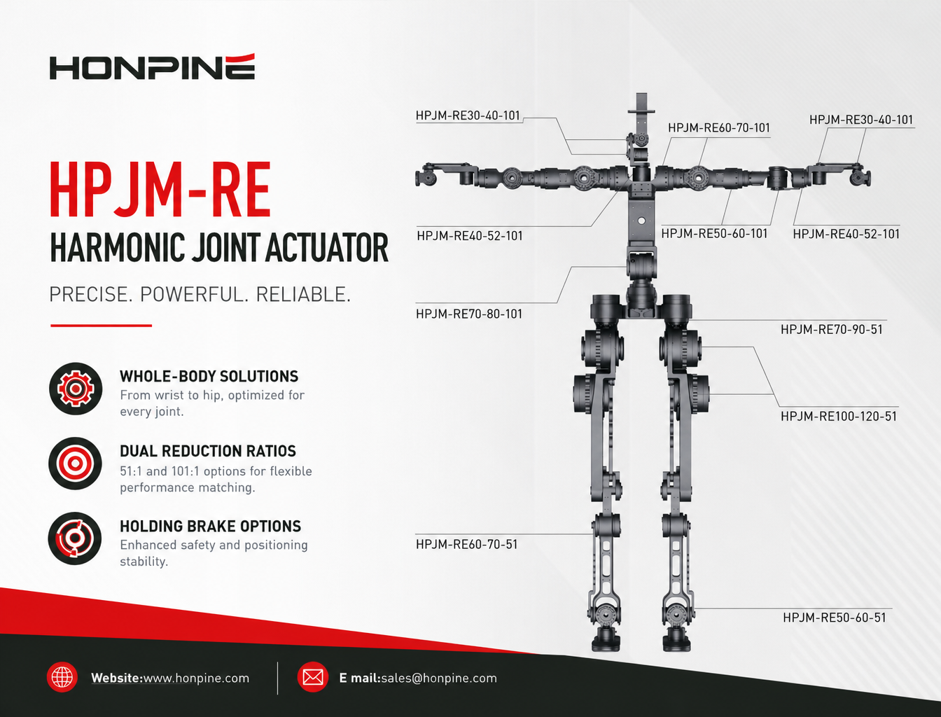
A preliminary configuration may use the HPJM30-40-PRO-101 at the wrist, HPJM40-52-PRO-101 at the elbow, HPJM60-70-PRO-101 at the shoulder, and HPJM50-60-PRO-101 at a waist axis.
These are engineering starting points rather than universal specifications. Final selection must account for the actual torque-speed curves, mechanical interfaces, encoder options, thermal limits, and duty cycles of each model.
3. Complete Lower-Body Joint Selection: Torque Capacity and Dynamic Response
The lower body must support the robot’s weight while controlling balance and responding to changing ground conditions. Hip, knee, and ankle joints therefore require careful evaluation of continuous torque, peak torque, output speed, acceleration, and impact loads.
Lower-body actuators should not be selected simply by choosing the largest frame size or the lowest reduction ratio. The complete torque-speed envelope and the robot’s motion-control strategy must be considered.
3.1 Knee Joint: HPJM100-120-PRO-51
The knee is a major load-bearing joint during walking, squatting, standing up, and recovering from balance disturbances.
Depending on the robot’s geometry and gait, knee torque can rise substantially during single-leg support, deep squatting, rapid acceleration, or landing. The actuator must handle both sustained loading and short-duration dynamic peaks.
The HPJM100-120-PRO-51 is a candidate for knee applications that require high torque capacity and dynamic response.
The 51:1 reduction configuration may provide a useful balance between torque multiplication and output speed when compared with a higher reduction ratio using an otherwise comparable drive system. However, actual speed and peak torque must be verified using the specific model’s performance data.
Key engineering checks include:
Continuous knee torque during standing and walking
Peak torque during squatting, rising, and recovery movements
Output speed and acceleration during the intended gait
Thermal performance under repetitive loading
Mechanical stiffness and permissible shock loading
Regenerative braking and DC bus behavior during deceleration
Selection consideration: A 101:1 ratio is not inherently unsuitable for every knee joint. The correct ratio depends on the required speed, torque, motor characteristics, and control bandwidth. A 51:1 option may be preferable for a high-dynamic design, but this must be confirmed through torque-speed and motion-profile analysis.
3.2 Hip Joint: HPJM70-80-PRO-51 or HPJM70-80-PRO-101
The hip is one of the most mechanically demanding areas of a humanoid robot. Depending on the architecture, it may include pitch, roll, and yaw axes.
Although these axes share the same general anatomical region, their operating conditions can differ significantly.
Hip pitch and roll
Pitch and roll axes often contribute directly to leg swing, body support, lateral balance, and recovery from disturbances. They may require substantial torque and rapid dynamic response.
The HPJM70-80-PRO-51 is a candidate for these axes when the required output speed and acceleration justify the lower reduction ratio.
Hip yaw
The yaw axis controls rotation around the vertical axis. Depending on the robot’s gait and turning strategy, it may prioritize controlled orientation and positioning over the highest possible output speed.
The HPJM70-80-PRO-101 is a candidate where its torque-speed characteristics satisfy the yaw axis requirements and the higher reduction ratio is beneficial to the intended control strategy.
Not every humanoid robot requires the same three-axis hip configuration. Some architectures use different actuator sizes or mechanical arrangements to reduce mass, simplify control, or improve packaging.
3.3 Ankle Joint: HPJM60-70-PRO-51
The ankle controls foot orientation and contributes to balance, ground contact, and the transition between stance and swing phases.
During walking, the ankle must respond to changes in ground reaction forces and help regulate the robot’s center of mass. Its torque and speed requirements depend on foot geometry, walking speed, terrain, and the control strategy.
The HPJM60-70-PRO-51 is a candidate for ankle applications that require a combination of torque capacity and dynamic response.
A lower reduction ratio may help support faster output movement when the motor and drive system can deliver the required speed and torque.
When the robot uses foot-force or contact sensors, the ankle actuator can form part of a coordinated control system for controlled foot placement and ground contact. However, impact absorption and stable contact also depend on mechanical compliance, sensor bandwidth, control latency, and the overall leg structure.
Key selection considerations include:
Peak ankle torque during push-off and balance recovery
Output speed during walking and foot repositioning
Foot geometry and ground reaction forces
Impact loads and allowable shock levels
Coordination with knee and hip control loops
Thermal limits during continuous walking
3.4 Lower-Body Configuration Summary
The HPJM60, HPJM70, and HPJM100 size classes provide a preliminary framework for configuring ankle, hip, and knee joints.
A potential starting configuration is the HPJM60-70-PRO-51 for the ankle, HPJM70-80-PRO-51 or HPJM70-80-PRO-101 for the appropriate hip axes, and HPJM100-120-PRO-51 for a high-load knee application.
The final configuration should be validated against the robot’s total mass, leg length, payload, gait, ground-contact conditions, and required dynamic performance.
4. Holding Brake Selection for Humanoid Robot Joint Actuators
Holding brakes can help maintain joint position when the drive system is disabled or electrical power is lost. They are particularly relevant to joints that support gravity-loaded structures or must remain in a defined position during standby.
The HPJM series offers brake-equipped configurations where specified by the product model. The suffix -B identifies a brake-equipped version when that suffix is included in the applicable model designation.
Before ordering, confirm the exact model code, brake availability, holding torque, electrical requirements, and mechanical interface.
4.1 Upper-Body Joints: Brake Selection for Suspended Loads
Wrist, elbow, shoulder, and waist joints may need brakes when the robot must hold a suspended load or maintain posture without continuous motor torque.
For example, a shoulder supporting an extended arm may experience a significant gravitational moment when the drive is disabled. A suitable holding brake can help prevent uncontrolled movement under the specified load conditions.
Brake-equipped HPJM30, HPJM40, HPJM50, and HPJM60 configurations may therefore be worth considering for relevant upper-body axes.
However, not every upper-body joint requires a brake. The decision should account for the joint’s orientation, gravitational loading, failure behavior, and whether an uncontrolled movement could create a hazard.
For joints that operate primarily in short, continuously powered dynamic cycles, a brake-free configuration may reduce mass and simplify the system, provided that the overall safety design remains adequate.
4.2 Lower-Body Joints: Brakes and Gravity-Load Management
Hip, knee, and ankle joints can support a substantial portion of the robot’s weight. When the robot is stationary or loses power, uncontrolled joint movement may lead to posture collapse or a fall.
Brake-equipped HPJM70 and HPJM100 configurations may be appropriate for lower-body axes where holding the joint under power-off conditions is part of the safety strategy.
Nevertheless, a holding brake alone does not guarantee that the complete robot will remain upright after power loss. The result depends on the robot’s center of gravity, joint geometry, brake torque, structural loading, and whether additional support or a controlled lowering strategy is provided.
For commercial humanoid robots, brake sizing and failure analysis should be incorporated into the overall risk assessment rather than treated as a simple model-selection decision.
4.3 Four Important Benefits of an Integrated Holding Brake
Power-off holding
A properly sized brake can help prevent unwanted joint movement when electrical power is removed, reducing the risk of a suspended arm or load moving unexpectedly.
Reduced holding power consumption
Once engaged, a suitable holding brake can maintain position without requiring the motor to continuously generate holding torque. This can reduce stationary power consumption and heat generation.
Safer maintenance and commissioning
Brake control can support defined procedures for maintenance, setup, and joint positioning. Manual release, where available, must follow the manufacturer’s instructions and applicable safety procedures.
Coordination with servo control
The brake release and engagement sequence should be coordinated with motor torque establishment, servo enable signals, and fault handling. Incorrect timing can cause sudden movement, mechanical shock, or loss of posture.
For vertical or gravity-loaded joints, engineers should verify the brake’s rated holding capacity and the complete system’s behavior during emergency stops, drive faults, and power interruptions.
5. How to Validate an HPJM Harmonic Joint Actuator Configuration
A complete humanoid robot joint solution requires more than assigning a model to each anatomical position. Engineers should verify the mechanical and electrical performance of every actuator under the robot’s actual operating conditions.
5.1 Calculate Required Joint Torque
Begin with the gravitational moment generated by the connected links and payload. For a simplified static case, the gravitational torque can be estimated from the perpendicular distance between the joint axis and the load’s center of gravity.
Dynamic torque must also account for acceleration, rotational inertia, friction, external contact forces, and the robot’s movement.
For legged robots, use gait simulation or inverse dynamics where possible. Peak joint torque can change substantially throughout the motion cycle.
5.2 Check the Torque-Speed Envelope
Rated torque and peak torque are not sufficient to establish whether an actuator can perform a specific movement.
Check the required output torque at the required output speed, including acceleration and deceleration phases. Confirm that peak torque is permitted for the required duration and repetition rate.
A configuration that meets peak torque requirements may still be unsuitable if its continuous thermal capacity or high-speed torque is insufficient.
5.3 Evaluate Reduction Ratio and Control Requirements
A 51:1 or 101:1 configuration should be evaluated according to the required joint speed, torque multiplication, reflected inertia, friction, and control performance.
For applications involving compliant interaction or force control, also consider torque sensing, encoder feedback, control-loop frequency, communication latency, and the mechanical compliance of the complete joint assembly.
Do not assume that reduction ratio alone determines force-control quality or the ability to absorb impacts.
5.4 Confirm Mechanical Integration and Electrical Compatibility
Before finalizing a model, verify:
Mounting dimensions and available installation space
Hollow-shaft requirements and cable routing
Rated voltage and current requirements
Encoder configuration and feedback compatibility
Communication protocol and controller support
Brake voltage, holding torque, and control sequence
Thermal management and environmental requirements
Mechanical compatibility and controller integration are especially important when several actuator sizes are used in one humanoid robot.
5.5 Validate Safety and Reliability
Run simulations and physical tests that represent the intended operating conditions, including standing, walking, squatting, lifting, turning, emergency stopping, and power-loss scenarios where applicable.
Assess continuous loading, peak loading, thermal rise, brake behavior, mechanical fatigue, and the consequences of a single-joint fault.
The final selection should be based on verified product specifications and system-level testing, not on frame size or reduction ratio alone.
6. Why Consider the HONPINE HPJM Harmonic Joint Actuator Series?
The HPJM series provides an integrated joint-drive platform for humanoid robot developers who need to distribute actuator capacity across multiple joints.
Different frame sizes and reduction ratios can support different combinations of installation space, torque requirements, and motion characteristics. This enables engineers to develop a coordinated joint architecture rather than using one actuator specification throughout the entire robot.
When evaluating the HPJM series, engineers should compare the exact model specifications, including rated and peak torque, output speed, mass, dimensions, encoder configuration, brake options, and communication interfaces.
The most suitable configuration is the one that satisfies the application’s mechanical, control, thermal, and safety requirements while minimizing unnecessary mass and complexity.
7. Get a Humanoid Robot Joint Actuator Solution from HONPINE
Designing a humanoid robot requires coordination between the upper-body manipulation system and the lower-body locomotion system. Wrist and elbow joints may prioritize compact integration and controlled positioning, while the hip, knee, and ankle must satisfy the torque and dynamic requirements of walking and balance control.
The HONPINE HPJM harmonic joint actuator series offers a starting point for developing these joint-specific configurations.
If you are developing a humanoid robot, robotic arm, quadruped robot, or other advanced robotic platform, contact HONPINE to discuss your joint requirements and actuator selection.
Our team can help evaluate suitable HPJM models, reduction ratios, brake configurations, and integration requirements based on your application.
Contact HONPINE for humanoid robot harmonic joint actuator selection and customized joint-drive solutions.

About Author
Theodore Li serves as the Technical Director at HONPINE, overseeing the R&D strategy for replication products, guiding team selection, and managing both pre-sales and after-sales operations.

Read More
Learn more about the story of HONPINE and industry trends related to precision transmission.
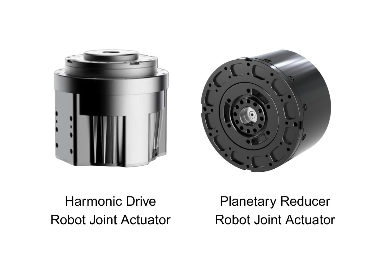
 What is robot joint actuator?How to Choose the Best Robot Rotary Joint Actuator?In core robot joint transmission solutions, planetary and harmonic rotary actuators each have their own strengths. Choosing the right type based on application requirements is essential to achieve the optimal balance between performance and cost.
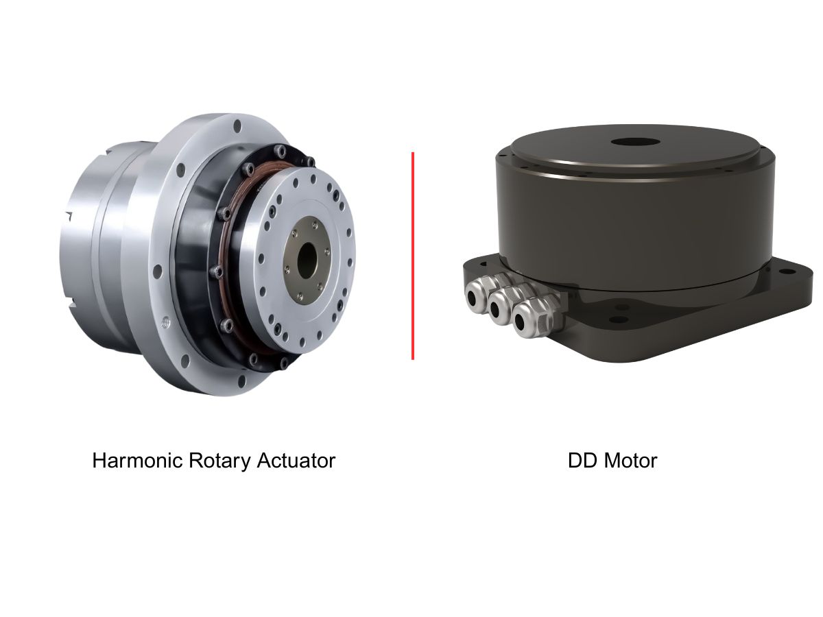
 DD Motors VS Harmonic Rotary ActuatorsThis article provides an in-depth comparison between Direct Drive (DD) motors and harmonic rotary actuators, covering their transmission principles, advantages and disadvantages, and typical application fields.
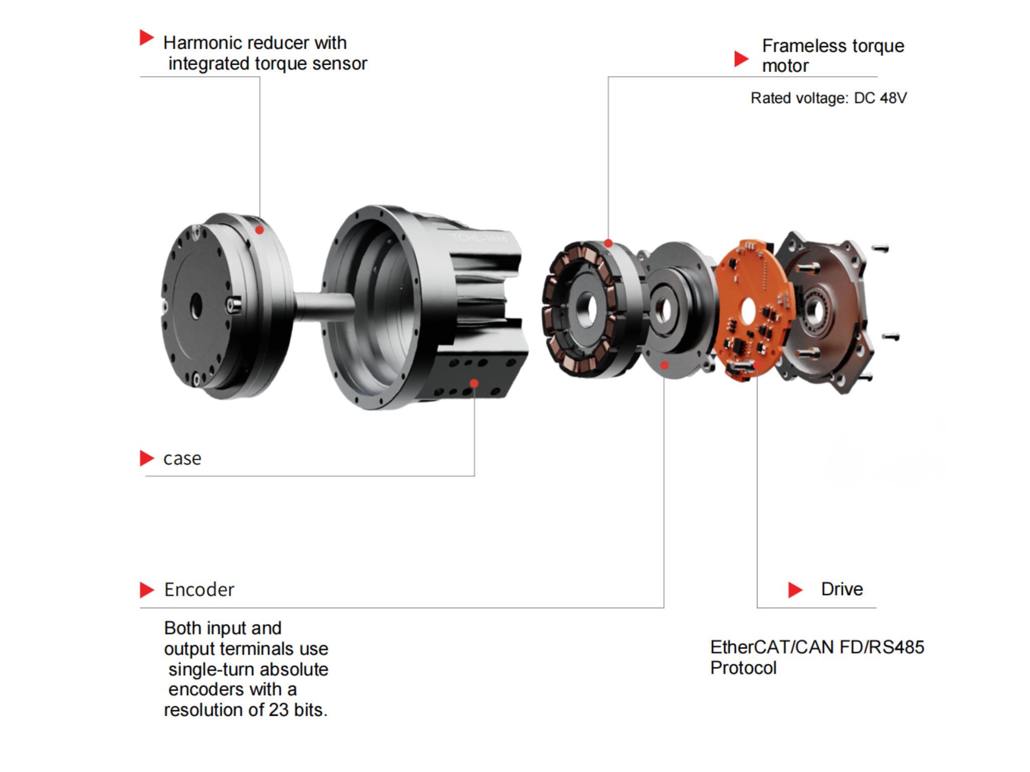
 OMG Ultra Compact Harmonic Drive Joint Module with Built-in Torque SensorHONPINE TCHL series harmonic drive joint module is a game-changing product that achieves disruptive improvements in multiple aspects such as lightweight design, integration level, and connection convenience. This article will analyze its revolutionary enhancements with you.
 The Role of Harmonic Drive Gears in Achieving 5–10 μm Accuracy in Dental Milling MachinesA dental milling machine is a CNC machining system used to directly process digital dental models into restorations such as crowns, bridges, veneers, inlays, and implant abutments. Dental milling machines require far higher operational accuracy and motion stability than ordinary equipment. This article explains how harmonic drive gear help dental milling machines achieve stable, continuous, and controllable operation.
 Why Are Harmonic Rotary Actuators Perfect for Medical Equipment?Harmonic rotary actuators (typically integrated systems consisting of a harmonic drive reducer, frameless torque motor, encoder, and optional brake) are regarded as key components in medical equipment. The core reason is that they simultaneously meet the most stringent medical requirements for precision, compact size, safety, and controllability. The following explanation is structured from three perspectives: technical characteristics, application scenarios, and medical value.
 High-Precision RV Reducers Perfectly Matched for Walking RobotsThe walking axis of a robot is a core component for power transmission and support. RV reducers provide extremely high rigidity, precision, and torque while maintaining a compact size and exceptional reliability, making them an ideal match for the demanding requirements of walking robot joints in terms of load capacity, impact resistance, and precision.
 The Complete Harmonic Joint Actuator Solution for Humanoid Robots: HPJM Series Selection GuideA complete guide to selecting harmonic joint actuators for humanoid robots. Explore HONPINE HPJM models for wrist, elbow, shoulder, waist, hip, knee, and ankle joints, with practical considerations for torque capacity, reduction ratios, dynamic response, and holding brake configurations.
 Why Are Harmonic Drive Actuators Ideal for Space-Constrained Industrial Automation Equipment?In modern industrial automation, limited installation space often makes mechanical design more challenging. Harmonic drive actuators offer a compact motion-control solution by integrating key drive components into a single unit. Their high reduction ratios, streamlined mechanical structures, and flexible mounting options can help equipment manufacturers reduce space requirements, simplify assembly, and optimize internal layouts. This article explores four ways integrated harmonic drive actuators support space-saving designs in industrial automation equipment.
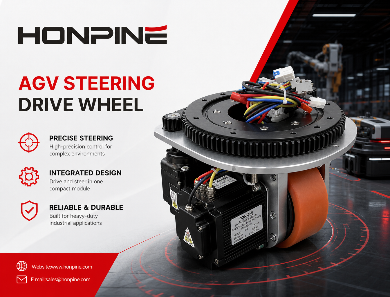
 AGV Robot Steering Drive Wheel: A Comprehensive Guide to Components, Applications, and SelectionAn AGV steering drive wheel integrates traction and active steering to support flexible movement in industrial mobile robots. This guide explains its main components, working principles, industrial applications, and key selection factors, including load capacity, traction torque, steering torque, wheel diameter, speed, and control interfaces. Discover how to choose a suitable steering drive module for AGVs, AMRs, autonomous forklifts, and heavy-duty material handling systems.
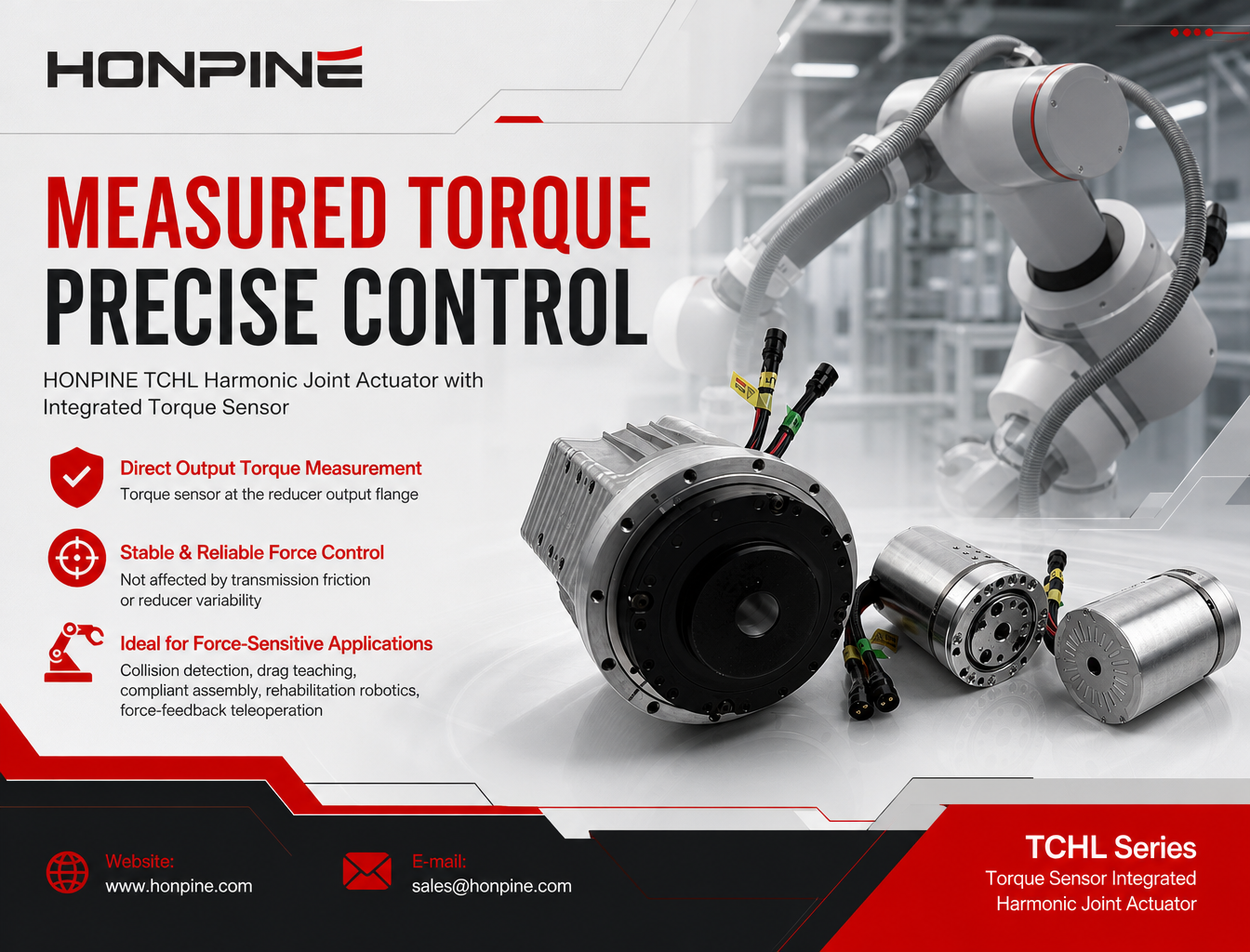
 How Does a Harmonic Joint Actuator with a Torque Sensor Improve Robot Force Control?Learn how the HONPINE TCHL harmonic joint actuator uses an integrated output torque sensor to support force feedback, collision detection, compliant assembly, rehabilitation robotics, and teleoperation.
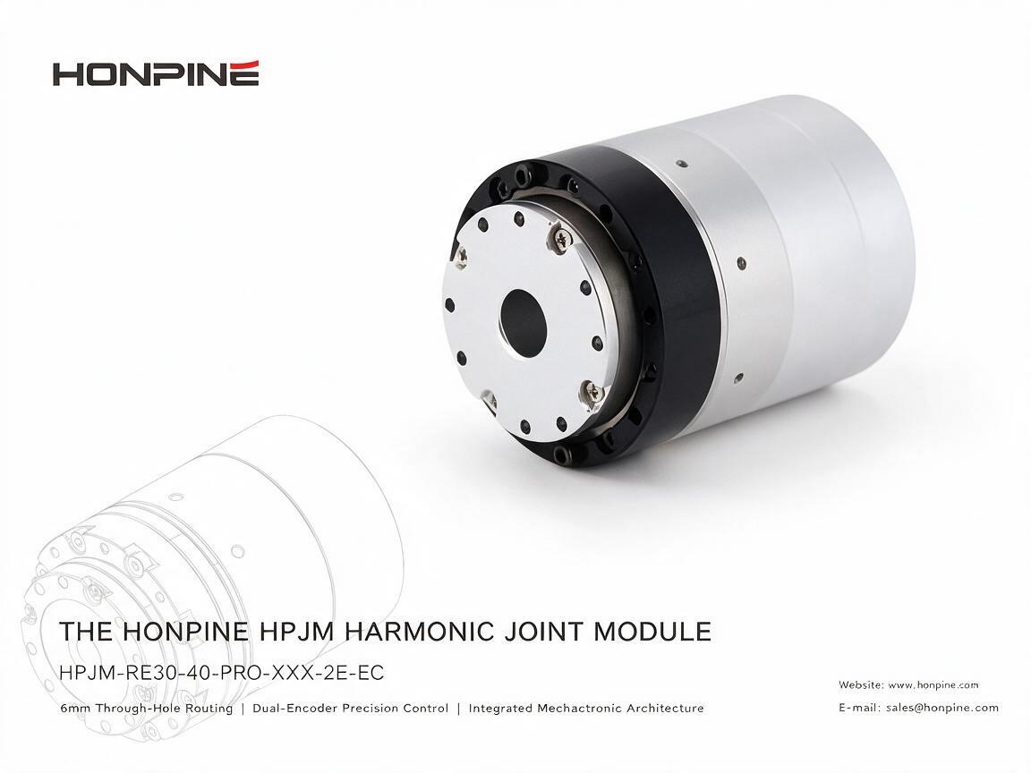
 Ultra-Compact Harmonic Joint Module with a 6 mm Hollow ShaftAs humanoid robots and compact robotic systems evolve, joint modules must deliver high torque density, precise motion control, and flexible cable routing within increasingly limited installation space. The HONPINE HPJM-RE30-40-PRO harmonic joint module addresses these challenges with a compact design, a 6 mm hollow shaft, dual-encoder feedback, and an integrated motor and FOC drive. In this article, we explore its key design features and explain how its hollow-shaft structure, EtherCAT connectivity, and flexible mounting options support the development of humanoid robots, drones, optical platforms, and precision automation equipment.
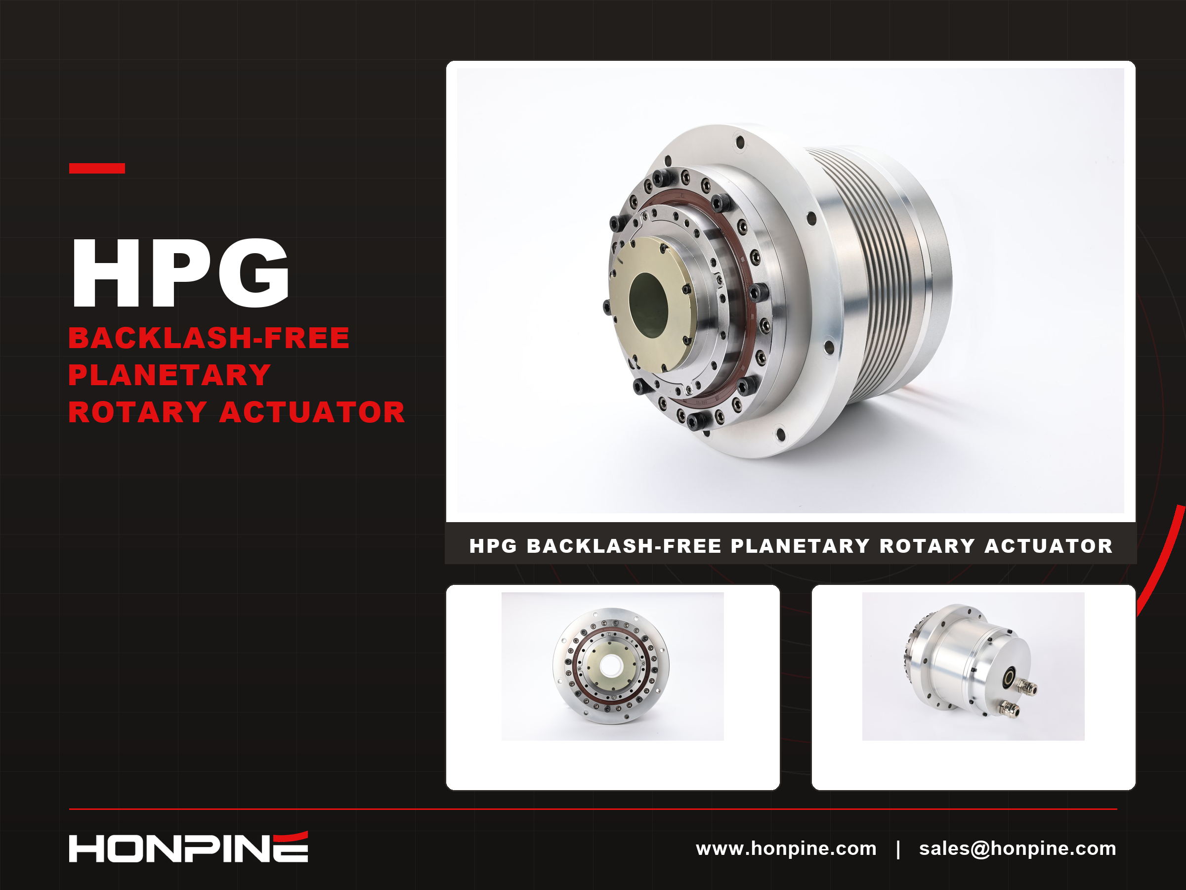
 How Does the HONPINE HPG Backlash-Free Planetary Rotary Actuator Balance CNC Accuracy and Rigidity?Discover the HONPINE HPG precision backlash-free planetary rotary actuator for CNC rotary tables. Explore positioning accuracy, torsional rigidity, low backlash, and drive selection.
Double Click
We provide harmonic drive reducer,planetary reducer,robot joint motor,robot rotary actuators,RV gear reducer,robot end effector,dexterous robot hand
 What is robot joint actuator?How to Choose the Best Robot Rotary Joint Actuator?In core robot joint transmission solutions, planetary and harmonic rotary actuators each have their own strengths. Choosing the right type based on application requirements is essential to achieve the optimal balance between performance and cost.
 DD Motors VS Harmonic Rotary ActuatorsThis article provides an in-depth comparison between Direct Drive (DD) motors and harmonic rotary actuators, covering their transmission principles, advantages and disadvantages, and typical application fields.
 OMG Ultra Compact Harmonic Drive Joint Module with Built-in Torque SensorHONPINE TCHL series harmonic drive joint module is a game-changing product that achieves disruptive improvements in multiple aspects such as lightweight design, integration level, and connection convenience. This article will analyze its revolutionary enhancements with you.
 The Complete Harmonic Joint Actuator Solution for Humanoid Robots: HPJM Series Selection GuideA complete guide to selecting harmonic joint actuators for humanoid robots. Explore HONPINE HPJM models for wrist, elbow, shoulder, waist, hip, knee, and ankle joints, with practical considerations for torque capacity, reduction ratios, dynamic response, and holding brake configurations.
 Why Are Harmonic Drive Actuators Ideal for Space-Constrained Industrial Automation Equipment?In modern industrial automation, limited installation space often makes mechanical design more challenging. Harmonic drive actuators offer a compact motion-control solution by integrating key drive components into a single unit. Their high reduction ratios, streamlined mechanical structures, and flexible mounting options can help equipment manufacturers reduce space requirements, simplify assembly, and optimize internal layouts. This article explores four ways integrated harmonic drive actuators support space-saving designs in industrial automation equipment.
 AGV Robot Steering Drive Wheel: A Comprehensive Guide to Components, Applications, and SelectionAn AGV steering drive wheel integrates traction and active steering to support flexible movement in industrial mobile robots. This guide explains its main components, working principles, industrial applications, and key selection factors, including load capacity, traction torque, steering torque, wheel diameter, speed, and control interfaces. Discover how to choose a suitable steering drive module for AGVs, AMRs, autonomous forklifts, and heavy-duty material handling systems.
 How Does a Harmonic Joint Actuator with a Torque Sensor Improve Robot Force Control?Learn how the HONPINE TCHL harmonic joint actuator uses an integrated output torque sensor to support force feedback, collision detection, compliant assembly, rehabilitation robotics, and teleoperation.
 Ultra-Compact Harmonic Joint Module with a 6 mm Hollow ShaftAs humanoid robots and compact robotic systems evolve, joint modules must deliver high torque density, precise motion control, and flexible cable routing within increasingly limited installation space. The HONPINE HPJM-RE30-40-PRO harmonic joint module addresses these challenges with a compact design, a 6 mm hollow shaft, dual-encoder feedback, and an integrated motor and FOC drive. In this article, we explore its key design features and explain how its hollow-shaft structure, EtherCAT connectivity, and flexible mounting options support the development of humanoid robots, drones, optical platforms, and precision automation equipment.
 How Does the HONPINE HPG Backlash-Free Planetary Rotary Actuator Balance CNC Accuracy and Rigidity?Discover the HONPINE HPG precision backlash-free planetary rotary actuator for CNC rotary tables. Explore positioning accuracy, torsional rigidity, low backlash, and drive selection.
 Why Are DD Torque Motors Ideal for High-End Five-Axis Rotary Tables?Choosing the right drive mechanism is critical to the performance of a five-axis rotary table. Worm gears, cam roller drives, harmonic reducers, RV cycloidal reducers, and DD torque motors each offer different advantages in positioning accuracy, torsional stiffness, speed, and cost. For high-end CNC machining, the challenge is not simply achieving low backlash, but maintaining accuracy under cutting loads and during continuous multi-axis motion. This article compares five common drive technologies and explains why direct-drive torque motors are an attractive option for applications requiring high dynamic response, reduced transmission errors, and consistent machining performance.
 Harmonic Drive Actuator Accuracy: Why It Should Be Evaluated at Four LevelsHarmonic drive actuator accuracy involves more than encoder resolution. Why should engineers evaluate it at four levels? Resolution, repeatability, unidirectional positioning accuracy, and bidirectional positioning accuracy describe different aspects of motion performance. Understanding these differences helps engineers select harmonic rotary actuators for semiconductor equipment, EFEM systems, and 3C automation without confusing theoretical encoder increments with actual positioning performance.
 Why Do Many Customers Choose HONPINE HPJM Harmonic Joint Modules for Just 2 mm More Hollow Bore Diameter?Why do many customers choose HONPINE HPJM harmonic joint modules for just 2 mm more hollow bore diameter? In compact robotic joints, this small dimensional difference can create a surprisingly large increase in available space. Because the cross-sectional area of a circular bore increases with the square of its diameter, an extra 2 mm can significantly improve internal cable routing and simplify system integration. This article examines the impact of hollow bore diameter, compares selected HONPINE HPJM models with comparable harmonic joint modules, and explains why bore size matters in humanoid robots, collaborative robots, and industrial automation.