







RV Reducer for Welding Positioners: Selection and Torque Calculation for Heavy-Duty Welding Applications
Introduction
A welding positioner is a critical motion component in automated welding systems. By rotating and repositioning a workpiece, it allows the welding robot or operator to maintain a suitable welding angle throughout the process. For heavy-duty welding positioners, however, the rotary drive must handle much more than simple speed reduction. It must provide sufficient output torque, high torsional rigidity, stable low-speed rotation, accurate positioning, and reliable performance during frequent acceleration, deceleration, and reversing.
For this reason, an RV reducer is widely considered a suitable transmission solution for medium- and heavy-duty welding positioners. Compared with conventional gear reducers, an RV gear reducer can provide high torque density, high rigidity, low backlash, and strong resistance to shock loads in a relatively compact package.
This article explains how to select an RV reducer and servo motor for a welding positioner by considering workpiece mass, rotary radius, output speed, load torque, inertia, acceleration, and positioning requirements.
Why Use an RV Reducer for a Welding Positioner?
A welding positioner typically operates at relatively low output speed while requiring high torque at the rotary axis. At the same time, the workpiece may weigh hundreds or even thousands of kilograms.
The drive system therefore needs to convert the high-speed, relatively low-torque output of a servo motor into controlled, high-torque rotary motion.
An RV reducer is particularly suitable for this application because it combines several characteristics that are important for welding positioners:
High reduction ratios
High output torque
High torsional rigidity
Low backlash
High torque density
Good resistance to shock loads
Stable operation during low-speed rotation
Compatibility with servo motor positioning systems
The correct RV gearbox, however, should not be selected based on workpiece weight alone. The actual calculation should consider the complete mechanical and motion profile of the welding positioner.
Typical Design Parameters for a Welding Positioner
Consider a head-and-tailstock welding positioner with the following preliminary specifications:
The purpose of this calculation is to determine the approximate reduction ratio, motor torque, and RV reducer torque capacity required for the rotary axis.
In an actual machine, the values should be replaced by the real workpiece geometry, center-of-gravity position, fixture mass, inertia, acceleration time, and operating cycle.
RV Reducer Selection and Torque Calculation
Step 1: Calculate the Required Output Speed
The maximum rotary speed is specified as:
70°/s
Converting angular velocity into revolutions per minute:
nL = 70 / 360 × 60
Therefore:
nL ≈ 11.67 rpm
The welding positioner therefore requires an output speed of approximately 11.7 rpm at maximum operating speed.
This low output speed is one of the main reasons a high-ratio reducer is required between the servo motor and the rotary axis.
Step 2: Determine the RV Reducer Ratio
Assuming a servo motor with a rated speed of 3000 rpm:
i = nM / nL
Substituting the values:
i = 3000 / 11.67 ≈ 257
Therefore, a reduction ratio in the range of approximately 250:1 is suitable from a speed-matching perspective.
For example, with a 250:1 reduction ratio:
nL = 3000 / 250 = 12 rpm
The corresponding rotary speed is:
12 × 360 / 60 = 72°/s
The resulting maximum output speed is approximately 72°/s, which slightly exceeds the required 70°/s.
The actual reduction ratio should ultimately be selected according to the available RV reducer ratio, servo motor speed range, and required motion profile.
Step 3: Calculate the Workpiece Inertia
The rotational inertia of the workpiece has a significant influence on the dynamic torque required by the welding positioner.
For an initial engineering estimate, the load can be simplified as an equivalent mass located at a given rotary radius:
JL = m × R²
For a 500 kg workpiece with an equivalent radius of 0.6 m:
JL = 500 × 0.6²
Therefore:
JL = 180 kg·m²
This is only a preliminary approximation. In a real welding positioner, the total rotational inertia should also include the fixture, chuck, mounting plate, coupling, output shaft, and other rotating components.
For large or irregular workpieces, calculating the actual center of mass and moment of inertia will produce a much more reliable result.
Step 4: Calculate the Gravity Load Torque
If the workpiece center of gravity is offset from the rotary axis, gravity creates a static load torque.
The basic relationship is:
TL = m × g × e
where m is the workpiece mass, g is gravitational acceleration, and e is the perpendicular distance between the center of gravity and the rotary axis.
If the effective offset is assumed to be 600 mm:
TL = 500 × 9.81 × 0.6
Therefore:
TL ≈ 2943 N·m
This value represents the gravitational torque under the assumed eccentric-load condition.
It is important to distinguish between the physical radius of the workpiece and the center-of-gravity offset. If the workpiece center of gravity is close to the rotary axis, the actual gravity torque will be significantly lower than this conservative example.
This distinction is important when selecting an RV reducer for a real welding positioner.
Step 5: Consider Acceleration and Deceleration Torque
Static torque is only one part of the calculation.
During acceleration and deceleration, the rotary system must also overcome the inertia of the workpiece.
The inertial torque can be estimated using:
TJ = JL × α
where JL is the total rotational inertia and α is the angular acceleration at the workpiece side.
This means that two welding positioners carrying the same 500 kg workpiece may require completely different RV reducers if their acceleration times are different.
For example, a positioner designed for slow and smooth rotation may have relatively low dynamic torque, while a high-speed positioner with rapid acceleration and braking can generate substantially higher peak torque.
Therefore, the acceleration and deceleration profile should always be included in the final RV gearbox selection.
Step 6: Calculate the Required Servo Motor Torque
The output torque of the RV reducer can be approximated by:
Tout = TM × i × η
Therefore, the required motor torque is:
TM = Tout / (i × η)
Assuming:
TL = 2943 N·m
i = 250
η = 0.85
The motor-side torque becomes:
TM = 2943 / (250 × 0.85)
TM ≈ 13.85 N·m
If a preliminary safety factor of 2.0 is applied:
TM,rated = 13.85 × 2
TM,rated ≈ 27.7 N·m
Therefore, the servo motor should have a rated torque of approximately 28 N·m or higher under this assumed load condition.
A typical 11 kW servo motor operating at 3000 rpm provides approximately:
T = 9550 × P / n
T = 9550 × 11 / 3000
T ≈ 35 N·m
From this preliminary calculation, an 11 kW, 3000 rpm servo motor can provide sufficient rated torque for the assumed condition.
However, the final motor selection should also verify peak torque, overload capability, thermal capacity, encoder resolution, and the complete duty cycle.
Step 7: Select the RV Reducer by Output Torque
The RV reducer must be capable of continuously transmitting the required load torque while also handling transient torque during acceleration, deceleration, emergency stops, and reversing.
Using a preliminary safety factor of 2.0:
Tcontinuous ≥ 2943 × 2
Tcontinuous ≥ 5886 N·m
For a conservative peak-load check using three times the static load torque:
Tpeak ≥ 2943 × 3
Tpeak ≥ 8829 N·m
Therefore, for this assumed eccentric-load condition, an RV reducer with approximately:
Rated output torque ≥ 6000 N·m
and:
Peak torque capacity ≥ 9000 N·m
would be a reasonable starting point for further model selection.
The actual reducer should be selected according to the manufacturer's rated torque, allowable peak torque, service factor, input speed, life rating, and duty cycle.
Why Peak Torque Matters in Welding Positioners?
A welding positioner rarely operates at a constant speed.
A typical motion cycle may include:
Acceleration → constant-speed rotation → deceleration → stop → reverse rotation
During these transitions, the inertial torque of the workpiece can become significant.
Emergency stopping can create even higher transient loads.
For this reason, selecting an RV reducer only according to its continuous rated torque may result in an undersized transmission system.
The following parameters should be checked together:
Continuous output torque
Peak output torque
Input speed
Output speed
Load inertia
Acceleration and deceleration
Duty cycle
Radial and axial loads
Backlash and torsional rigidity
This approach provides a much more reliable basis for RV reducer selection.
RV Reducer Backlash and Positioning Accuracy
Positioning accuracy is another important consideration for automated welding positioners.
The mechanical transmission chain normally consists of:
Servo motor → RV reducer → output shaft → fixture → workpiece
Any mechanical error in this chain can influence the final workpiece position.
Backlash is particularly important because reversing the rotary direction can introduce an angular error between the input and output sides.
For example, assuming an angular error of 1 arcmin:
θ = 1 / 60 × π / 180
θ ≈ 0.000291 rad
At a rotary radius of 600 mm:
ΔL = θ × R
ΔL ≈ 0.000291 × 600
ΔL ≈ 0.175 mm
This example shows that when the application requires approximately 0.1 mm-level linear repeatability at the workpiece radius, reducer backlash alone may become an important factor.
However, system positioning accuracy cannot be determined from reducer backlash alone.
It also depends on:
Servo encoder resolution
Servo control performance
RV reducer transmission accuracy
Torsional deformation
Output shaft stiffness
Fixture rigidity
Installation accuracy
Workpiece deformation
Therefore, a high-resolution encoder does not automatically guarantee high mechanical positioning accuracy.
How to Improve Welding Positioner Positioning Performance?
Use a Low-Backlash, High-Rigidity RV Reducer
A reducer with low backlash and high torsional rigidity helps reduce angular movement caused by load changes and reversing motion.
Use a High-Resolution Absolute Encoder
An absolute encoder provides accurate feedback to the servo system and can reduce positioning uncertainty.
For applications requiring position retention after power loss, a multi-turn absolute encoder can also be considered.
Increase Output-Side Structural Rigidity
Even a high-performance RV reducer cannot compensate for excessive deformation in the output shaft, mounting plate, fixture, or machine frame.
The mechanical structure should therefore be designed with sufficient stiffness for the actual workpiece load.
Consider Output-Side Position Feedback
For high-precision welding positioners, direct position feedback at the output axis can provide more accurate information about the actual workpiece position than relying only on the motor-side encoder.
Single-Drive vs. Dual-Drive Welding Positioners
Head-and-tailstock welding positioners can use either a single rotary drive or a dual-drive configuration.
Single-Drive Welding Positioner
With a single-drive design, one drive system provides the primary rotary torque. The RV reducer, output shaft, bearing arrangement, and machine frame must therefore be designed to handle the complete load condition.
Dual-Drive Welding Positioner
A dual-drive configuration uses servo motors and reducers at both ends of the workpiece.
If the load is evenly distributed, each drive can theoretically handle approximately half of the total average torque.
However, the total load cannot simply be divided by two during final engineering design.
Differences in mechanical alignment, servo synchronization, stiffness, friction, and load distribution can cause unequal torque sharing between the two drive systems.
Therefore, a dual-drive welding positioner requires both mechanical synchronization and coordinated servo control.
Key Advantages of RV Reducers for Welding Positioners
High Torsional Rigidity
High torsional rigidity helps maintain stable workpiece positioning during welding and reduces angular deflection caused by changing loads.
High Torque Density
An RV gear reducer can deliver high output torque within a relatively compact housing, making it suitable for heavy-duty rotary axes where installation space is limited.
Low Backlash
Low backlash helps improve reversing accuracy and repeatable positioning, which is particularly important for robotic welding applications.
High Resistance to Shock Loads
Large workpieces can generate significant transient loads during acceleration, deceleration, loading, and emergency stopping. An appropriately sized RV reducer can provide the mechanical robustness required for these operating conditions.
Suitable for Servo-Controlled Motion
RV reducers can be combined with AC servo motors and high-resolution encoders to create closed-loop rotary positioning systems for automated welding equipment.
Example RV Reducer Selection for a 500 kg Welding Positioner
For the example considered in this article:
Based on these preliminary calculations, an RV reducer with a rated output torque around 6000 N·m or higher and sufficient peak torque capacity can be considered for further evaluation.
The exact reducer model should be confirmed after checking the actual workpiece center of gravity, total inertia, acceleration time, operating cycle, radial and axial loads, mounting configuration, and required service life.
Common Mistakes When Selecting an RV Reducer for a Welding Positioner
Selecting the Reducer Only According to Workpiece Weight
A 500 kg workpiece does not automatically require the same RV gearbox specification in every application.
The center-of-gravity offset, inertia, acceleration, and fixture geometry can significantly change the required torque.
Ignoring Dynamic Torque
Static gravity torque is not enough for applications involving rapid acceleration, braking, or reversing.
The inertial torque should be included in the final calculation.
Selecting by Motor Power Alone
An 11 kW servo motor does not automatically determine the correct RV reducer.
The reducer must be matched according to input speed, output torque, peak torque, reduction ratio, inertia, duty cycle, and mechanical loading.
Ignoring Backlash
A reducer can provide sufficient torque but still fail to meet the required positioning performance if its mechanical accuracy and rigidity are inadequate for the application.
Ignoring the Fixture and Rotating Structure
The workpiece is not the only rotating mass. Chucks, fixtures, mounting plates, couplings, shafts, and other components also contribute to the total rotational inertia.
Conclusion
Selecting an RV reducer for a welding positioner requires more than matching the reducer to the workpiece weight. The complete rotary system should be evaluated based on load torque, center-of-gravity offset, rotational inertia, acceleration, maximum speed, peak torque, backlash, torsional rigidity, and positioning requirements.
For the 500 kg welding positioner example discussed in this article, a maximum rotary speed of 70°/s corresponds to an output speed of approximately 11.67 rpm. When using a 3000 rpm servo motor, a reduction ratio around 250:1 provides an output speed of approximately 12 rpm.
Under the assumed 600 mm center-of-gravity offset, the calculated gravity torque is approximately 2943 N·m. With a preliminary safety factor, the continuous output torque requirement reaches approximately 5886 N·m, while a conservative peak-load check gives approximately 8829 N·m.
This provides a useful starting point for selecting a high-torque, high-rigidity RV gear reducer for heavy-duty welding positioners.
For actual machine design, however, these calculations should be refined using the real workpiece center of gravity, complete rotational inertia, acceleration and braking profile, fixture mass, radial and axial loads, operating cycle, and the specific technical data of the selected RV reducer.
A properly matched RV reducer and servo motor can provide the combination of high torque, precise positioning, stable low-speed rotation, and mechanical rigidity required for robotic welding positioners, welding rotators, and other heavy-duty automated rotary equipment.
Read More
Learn more about the story of HONPINE and industry trends related to precision transmission.
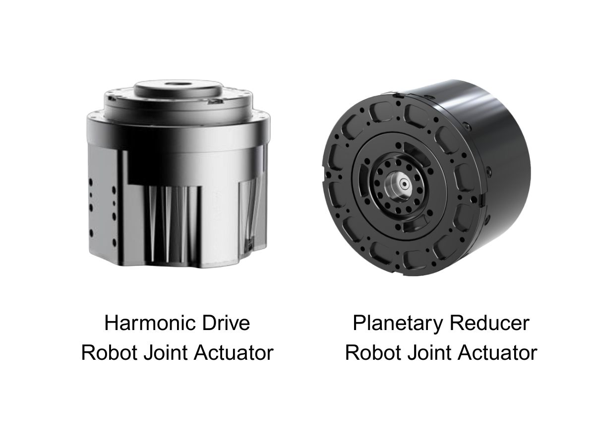
 What is robot joint actuator?How to Choose the Best Robot Rotary Joint Actuator?In core robot joint transmission solutions, planetary and harmonic rotary actuators each have their own strengths. Choosing the right type based on application requirements is essential to achieve the optimal balance between performance and cost.
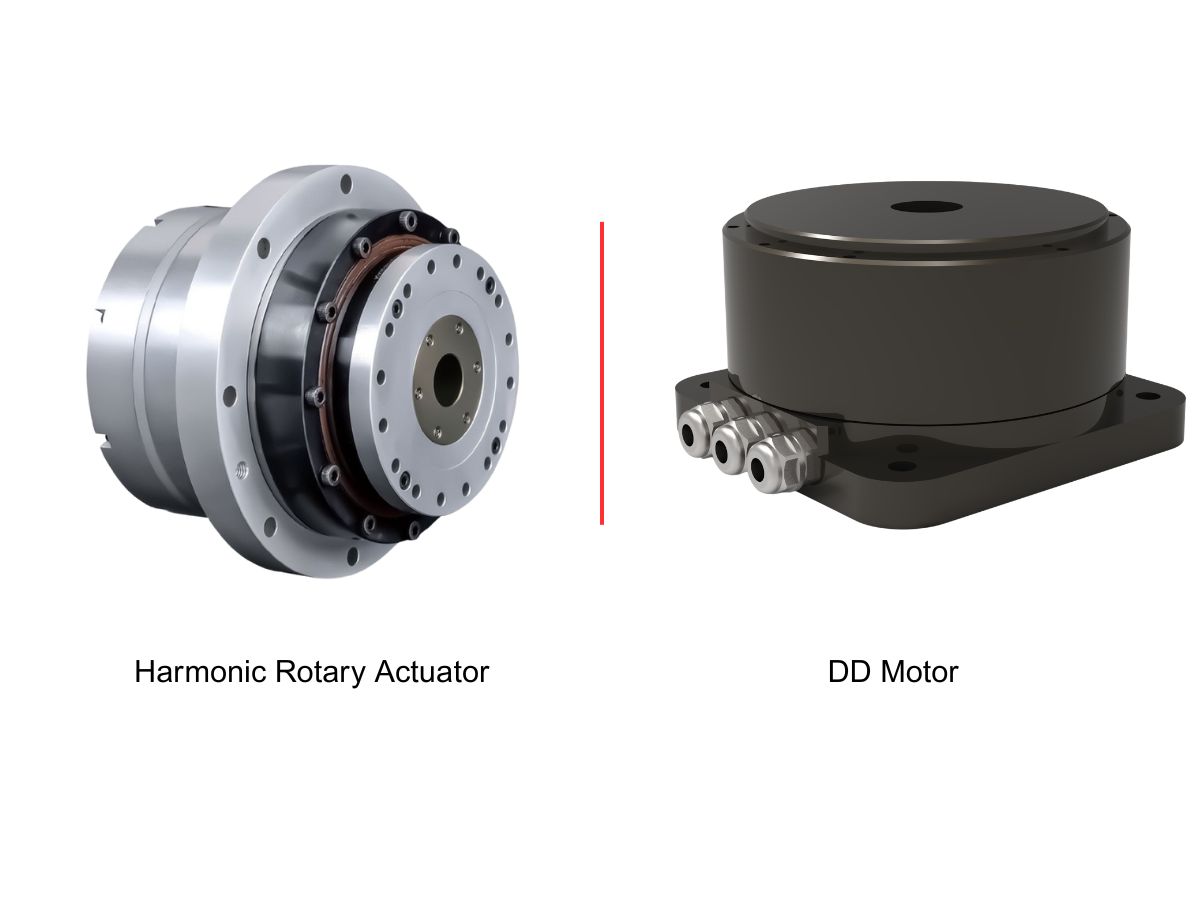
 DD Motors VS Harmonic Rotary ActuatorsThis article provides an in-depth comparison between Direct Drive (DD) motors and harmonic rotary actuators, covering their transmission principles, advantages and disadvantages, and typical application fields.
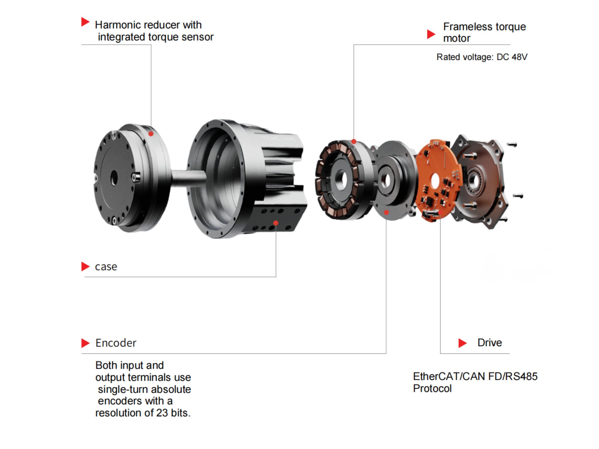
 OMG Ultra Compact Harmonic Drive Joint Module with Built-in Torque SensorHONPINE TCHL series harmonic drive joint module is a game-changing product that achieves disruptive improvements in multiple aspects such as lightweight design, integration level, and connection convenience. This article will analyze its revolutionary enhancements with you.
 The Role of Harmonic Drive Gears in Achieving 5–10 μm Accuracy in Dental Milling MachinesA dental milling machine is a CNC machining system used to directly process digital dental models into restorations such as crowns, bridges, veneers, inlays, and implant abutments. Dental milling machines require far higher operational accuracy and motion stability than ordinary equipment. This article explains how harmonic drive gear help dental milling machines achieve stable, continuous, and controllable operation.
 Why Are Harmonic Rotary Actuators Perfect for Medical Equipment?Harmonic rotary actuators (typically integrated systems consisting of a harmonic drive reducer, frameless torque motor, encoder, and optional brake) are regarded as key components in medical equipment. The core reason is that they simultaneously meet the most stringent medical requirements for precision, compact size, safety, and controllability. The following explanation is structured from three perspectives: technical characteristics, application scenarios, and medical value.
 High-Precision RV Reducers Perfectly Matched for Walking RobotsThe walking axis of a robot is a core component for power transmission and support. RV reducers provide extremely high rigidity, precision, and torque while maintaining a compact size and exceptional reliability, making them an ideal match for the demanding requirements of walking robot joints in terms of load capacity, impact resistance, and precision.
 HSG Laser Brings Next-Generation Cutting and Automation to FABTECH 2026HSG Laser at FABTECH 2026: Explore the TS2 PRO tube laser cutting machine and AI CutPilot automation, plus key procurement checks to guide your next equipment investment.
 How Does a Harmonic Joint Actuator with a Torque Sensor Improve Robot Force Control?Learn how the HONPINE TCHL harmonic joint actuator uses an integrated output torque sensor to support force feedback, collision detection, compliant assembly, rehabilitation robotics, and teleoperation.
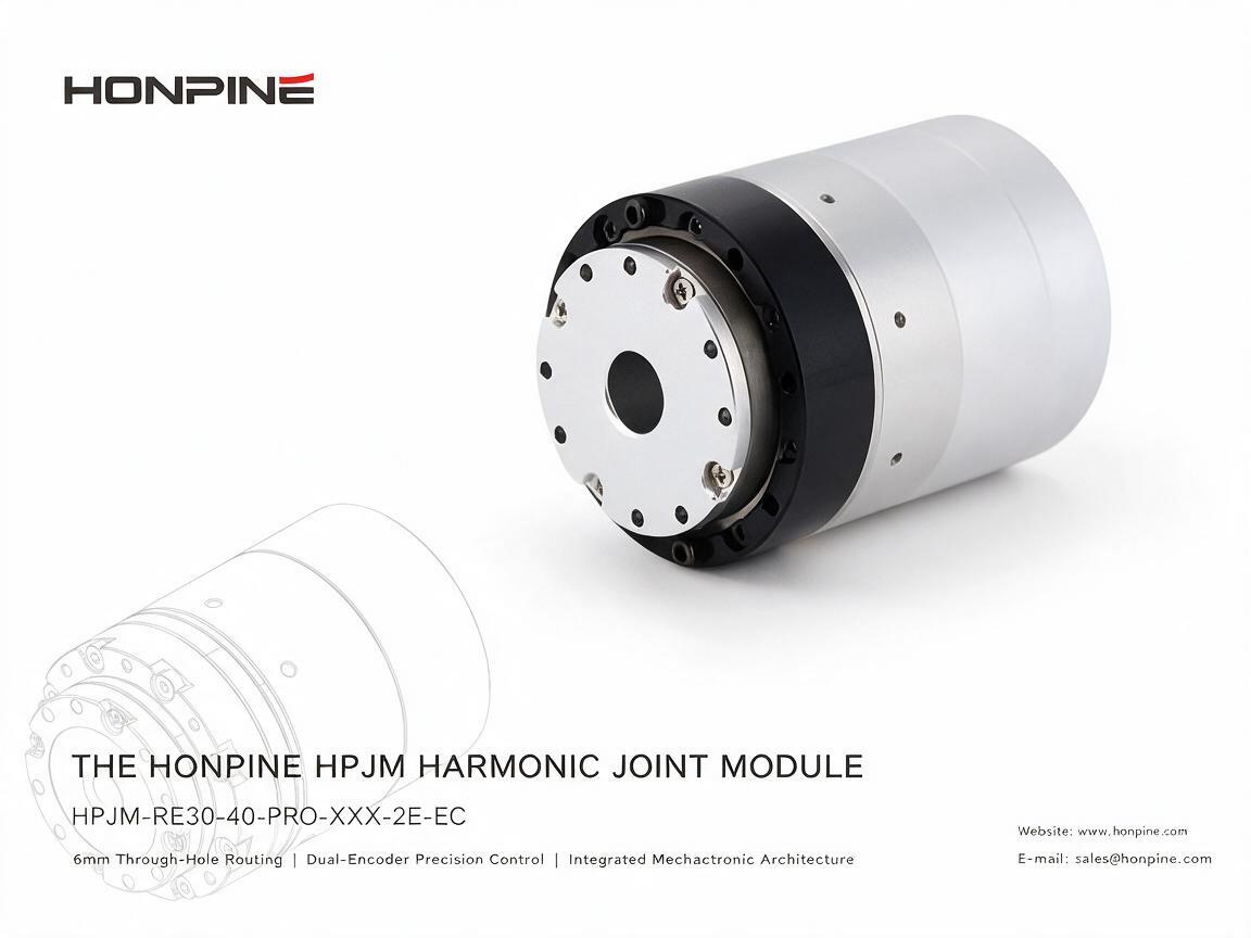
 Ultra-Compact Harmonic Joint Module with a 6 mm Hollow ShaftAs humanoid robots and compact robotic systems evolve, joint modules must deliver high torque density, precise motion control, and flexible cable routing within increasingly limited installation space. The HONPINE HPJM-RE30-40-PRO harmonic joint module addresses these challenges with a compact design, a 6 mm hollow shaft, dual-encoder feedback, and an integrated motor and FOC drive. In this article, we explore its key design features and explain how its hollow-shaft structure, EtherCAT connectivity, and flexible mounting options support the development of humanoid robots, drones, optical platforms, and precision automation equipment.
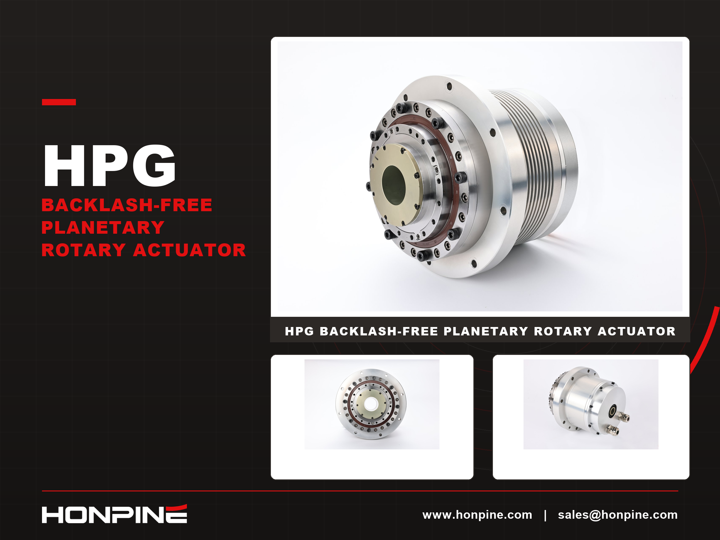
 How Does the HONPINE HPG Backlash-Free Planetary Rotary Actuator Balance CNC Accuracy and Rigidity?Discover the HONPINE HPG precision backlash-free planetary rotary actuator for CNC rotary tables. Explore positioning accuracy, torsional rigidity, low backlash, and drive selection.
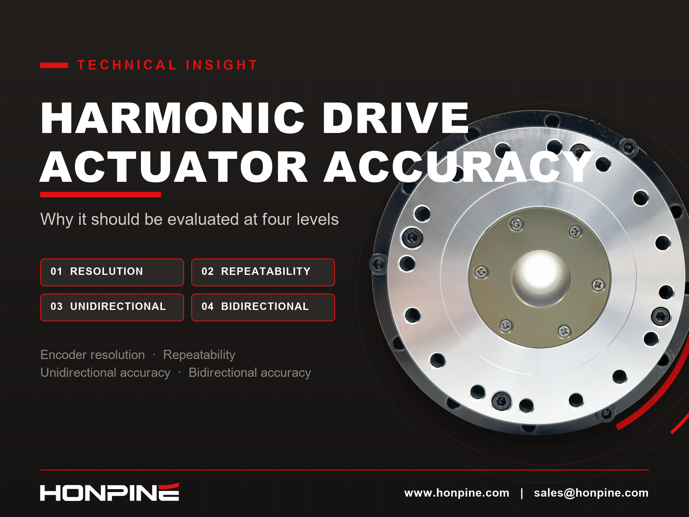
 Harmonic Drive Actuator Accuracy: Why It Should Be Evaluated at Four LevelsHarmonic drive actuator accuracy involves more than encoder resolution. Why should engineers evaluate it at four levels? Resolution, repeatability, unidirectional positioning accuracy, and bidirectional positioning accuracy describe different aspects of motion performance. Understanding these differences helps engineers select harmonic rotary actuators for semiconductor equipment, EFEM systems, and 3C automation without confusing theoretical encoder increments with actual positioning performance.
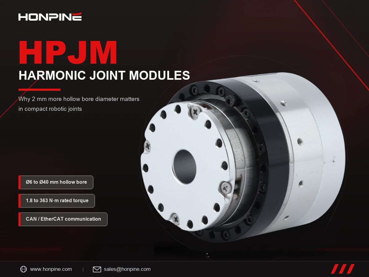
 Why Do Many Customers Choose HONPINE HPJM Harmonic Joint Modules for Just 2 mm More Hollow Bore Diameter?Why do many customers choose HONPINE HPJM harmonic joint modules for just 2 mm more hollow bore diameter? In compact robotic joints, this small dimensional difference can create a surprisingly large increase in available space. Because the cross-sectional area of a circular bore increases with the square of its diameter, an extra 2 mm can significantly improve internal cable routing and simplify system integration. This article examines the impact of hollow bore diameter, compares selected HONPINE HPJM models with comparable harmonic joint modules, and explains why bore size matters in humanoid robots, collaborative robots, and industrial automation.
Double Click
We provide harmonic drive reducer,planetary reducer,robot joint motor,robot rotary actuators,RV gear reducer,robot end effector,dexterous robot hand
 What is robot joint actuator?How to Choose the Best Robot Rotary Joint Actuator?In core robot joint transmission solutions, planetary and harmonic rotary actuators each have their own strengths. Choosing the right type based on application requirements is essential to achieve the optimal balance between performance and cost.
 DD Motors VS Harmonic Rotary ActuatorsThis article provides an in-depth comparison between Direct Drive (DD) motors and harmonic rotary actuators, covering their transmission principles, advantages and disadvantages, and typical application fields.
 OMG Ultra Compact Harmonic Drive Joint Module with Built-in Torque SensorHONPINE TCHL series harmonic drive joint module is a game-changing product that achieves disruptive improvements in multiple aspects such as lightweight design, integration level, and connection convenience. This article will analyze its revolutionary enhancements with you.
 How Does a Harmonic Joint Actuator with a Torque Sensor Improve Robot Force Control?Learn how the HONPINE TCHL harmonic joint actuator uses an integrated output torque sensor to support force feedback, collision detection, compliant assembly, rehabilitation robotics, and teleoperation.
 Ultra-Compact Harmonic Joint Module with a 6 mm Hollow ShaftAs humanoid robots and compact robotic systems evolve, joint modules must deliver high torque density, precise motion control, and flexible cable routing within increasingly limited installation space. The HONPINE HPJM-RE30-40-PRO harmonic joint module addresses these challenges with a compact design, a 6 mm hollow shaft, dual-encoder feedback, and an integrated motor and FOC drive. In this article, we explore its key design features and explain how its hollow-shaft structure, EtherCAT connectivity, and flexible mounting options support the development of humanoid robots, drones, optical platforms, and precision automation equipment.
 How Does the HONPINE HPG Backlash-Free Planetary Rotary Actuator Balance CNC Accuracy and Rigidity?Discover the HONPINE HPG precision backlash-free planetary rotary actuator for CNC rotary tables. Explore positioning accuracy, torsional rigidity, low backlash, and drive selection.
 Harmonic Drive Actuator Accuracy: Why It Should Be Evaluated at Four LevelsHarmonic drive actuator accuracy involves more than encoder resolution. Why should engineers evaluate it at four levels? Resolution, repeatability, unidirectional positioning accuracy, and bidirectional positioning accuracy describe different aspects of motion performance. Understanding these differences helps engineers select harmonic rotary actuators for semiconductor equipment, EFEM systems, and 3C automation without confusing theoretical encoder increments with actual positioning performance.
 Why Do Many Customers Choose HONPINE HPJM Harmonic Joint Modules for Just 2 mm More Hollow Bore Diameter?Why do many customers choose HONPINE HPJM harmonic joint modules for just 2 mm more hollow bore diameter? In compact robotic joints, this small dimensional difference can create a surprisingly large increase in available space. Because the cross-sectional area of a circular bore increases with the square of its diameter, an extra 2 mm can significantly improve internal cable routing and simplify system integration. This article examines the impact of hollow bore diameter, compares selected HONPINE HPJM models with comparable harmonic joint modules, and explains why bore size matters in humanoid robots, collaborative robots, and industrial automation.
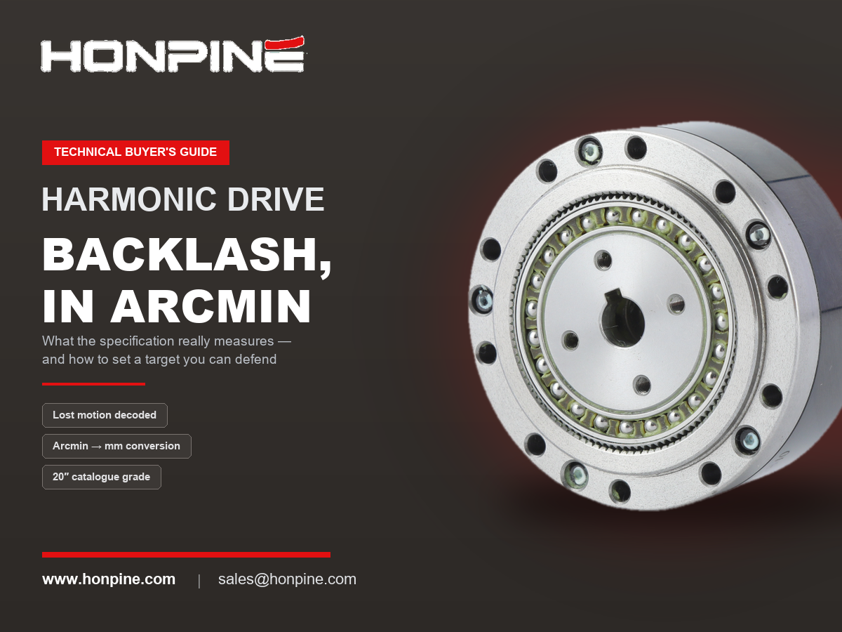
 Harmonic Drive Backlash in Arcmin: What the Specification Really Tells YouChoosing the right force control harmonic joint actuator involves more than comparing torque and dimensions. Torque sensor specifications, encoder feedback, communication protocols, functional safety, and hollow-shaft size can all affect system integration and control performance. In this guide, HONPINE Technical Director compares the TCHL and HAG harmonic joint actuator series, explaining their key differences and providing a practical selection framework for humanoid robots, collaborative manipulators, precision assembly, polishing, and other force-controlled applications.
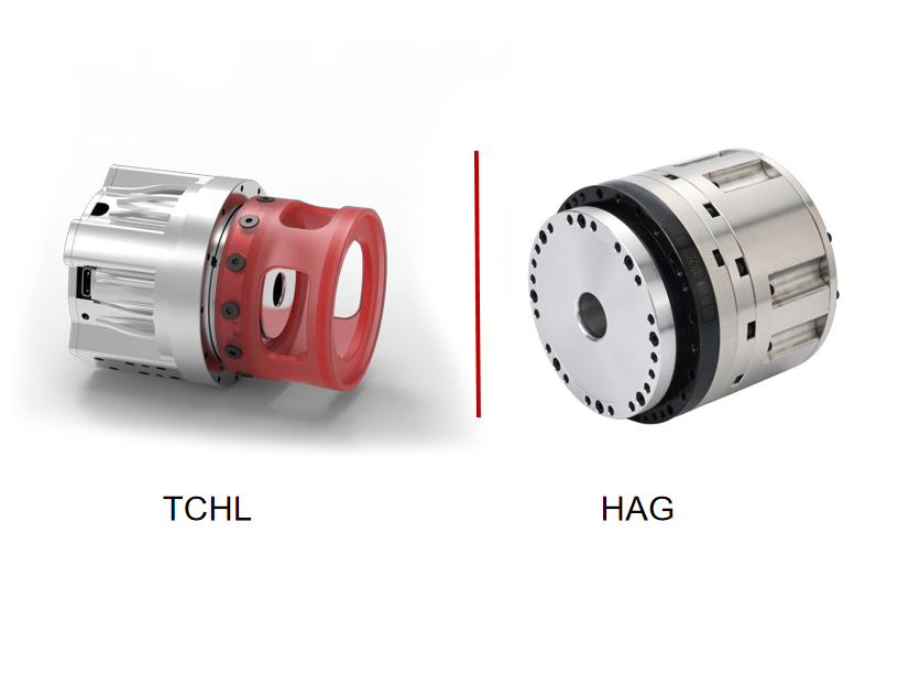
 How to Choose a Force Control Harmonic Joint Actuator? An In-Depth Comparison of HONPINE TCHL and HAGChoosing the right force control harmonic joint actuator involves more than comparing torque and dimensions. Torque sensor specifications, encoder feedback, communication protocols, functional safety, and hollow-shaft size can all affect system integration and control performance. In this guide, HONPINE Technical Director compares the TCHL and HAG harmonic joint actuator series, explaining their key differences and providing a practical selection framework for humanoid robots, collaborative manipulators, precision assembly, polishing, and other force-controlled applications.
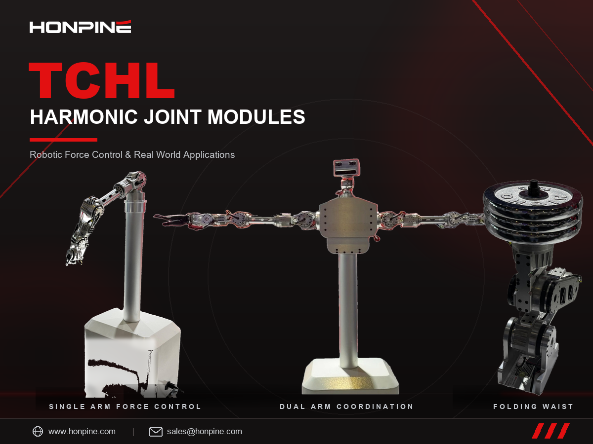
 HONPINE TCHL Harmonic Joint Modules: Robotic Force Control and Real-World ApplicationsHello everyone, I’m Theodore Li, Technical Director at HONPINE.
HONPINE TCHL harmonic joint modules have been deployed in a range of robotic motion-control applications, including dual-arm humanoid robots, single-arm compliant force control, and folding waist mechanisms for wheeled humanoid robots. As integrated motion components, they support a wide range of applications in robotics, intelligent manufacturing, and industrial automation.
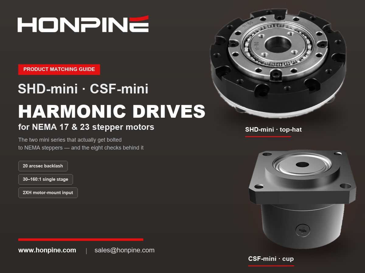
From core components to integrated motion units, HONPINE showcases the possibilities of precision transmission technology across different robotic applications through a diverse product portfolio and practical motion demonstrations. NEMA 17 & NEMA 23 Harmonic Drive Matching Guide: Pairing Stepper Motors with Harmonic ReducersPairing a stepper motor with a harmonic drive is not a budget compromise. A stepper's weak points — the coarse step angle, torque collapse above roughly 400 rpm, and the lack of a precision transmission — are exactly what a harmonic drive fixes: it pulls the operating point into the low-speed, high-torque sweet spot, refines a 1.8° step angle into arc-second resolution, and delivers near-zero backlash. This guide explains what NEMA frame sizes mean at the mounting interface, which harmonic frames match NEMA 17 and NEMA 23, the eight checks to run in order — including the input-side no-load starting torque most often missed — and the pairing's real weakness: silent failure. Includes HONPINE SHD and CSF specifications.