







NEMA 17 & NEMA 23 Harmonic Drive Matching Guide: Pairing Stepper Motors with Harmonic Reducers
A NEMA 17 stepper bolted to a 100:1 harmonic reducer is one of the most repeated pairings in desktop robotics, laboratory automation, and rotary indexing. It is also one of the most frequently mis-selected — because the checks that decide whether it works are not the ones people run first.
Here is the short version:
1. The pairing is popular because the two devices cover each other's weaknesses. A stepper gives cheap, simple, open-loop positioning; a harmonic drive converts that into high torque, arc-second-level resolution, and near-zero backlash.
2. Eight quantities must be matched, but three decide the outcome: the mounting interface, the input-side no-load starting torque, and the overload limits. The input-side starting torque is the one most often skipped — it is why a small stepper cannot turn a large harmonic frame, and it has nothing to do with the reduction ratio.
3. The real weakness is silent failure. An open-loop stepper loses steps without reporting an error, and a harmonic drive that exceeds its instantaneous allowable torque ratchets and permanently damages its tooth surfaces. Together, they mean a fault can occur with no signal at all. The engineering discipline is therefore: close the loop, or leave enough safety margin.
Why a Stepper Motor and a Harmonic Drive Are Paired So Often?
Three weak points a harmonic drive removes
Three commercial reasons OEMs keep choosing this pairing
Best cost structure. A stepper plus a pulse/direction driver costs far less than a servo motor, encoder, and servo drive. The harmonic drive is the largest single cost item, but the total is still well below a servo-plus-harmonic solution. Where precision requirements are high and dynamic performance requirements are low, this is the best value combination available.
No tuning. The pulse/direction interface needs no PID tuning and no encoder wiring. For OEM equipment, laboratory instruments, and low-volume products, both development time and the skill threshold drop sharply.
Mature, non-locking supply. NEMA frame sizes are a global commodity with multiple suppliers and easy substitution, and harmonic drives are standard products too. This pairing has the lowest barrier to re-sourcing and secondary development.
What "NEMA" Actually Means at the Mounting Interface
NEMA stands for the National Electrical Manufacturers Association. In motion control, a "NEMA motor" almost always means a stepper motor standardized to a NEMA frame size: the frame number is the flange width in inches. Because flange dimensions, mounting-hole spacing, and shaft diameter are all standardized, motors from different manufacturers are interchangeable — which is exactly why the frame size, not the brand, is the starting point for matching.
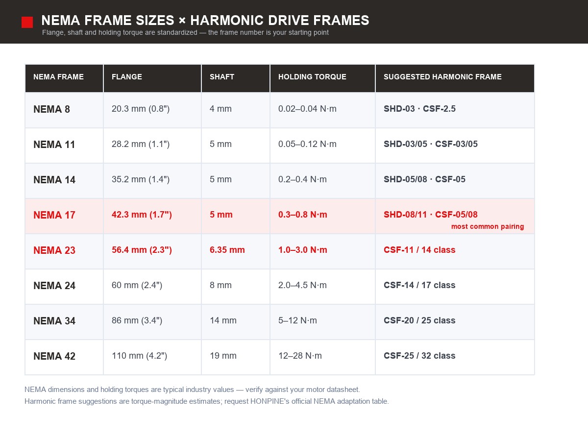
NEMA frame sizes and the harmonic frames that fit them
NEMA dimensions and holding torques are industry-typical values and vary between manufacturers — always design against the specification sheet of the specific motor you are using. The harmonic frame suggestions above are based on torque magnitude and are analytical estimates; HONPINE publishes the official per-frame adaptation table on request.
Flange, shaft and input type: why a direct-motor input matters
Three sub-items make up the interface, and if this step is wrong nothing calculated later matters:
1. Flange. The NEMA frame number fixes the flange size, mounting-hole spacing, and pilot diameter.
2. Input type. Harmonic reducers come in shaft input and direct-motor input versions. Direct-motor input (hollow input shaft plus clamping ring) is the shortest axially and needs no coupling; shaft input requires a separate coupling.
3. Shaft fit. Motor shaft diameter against the harmonic input bore tolerance (typically h7/H7), plus the key or clamping method.
In HONPINE's mini harmonic reducer part numbering, the input/output code identifies this directly. In a model such as CSF-05-XXX-2XH-A, 2XH means motor direct connection and 1U means shaft input; the output position A means flange, while B / C / D / E / U indicate shaft or other output forms. When matching a NEMA motor, choose the 2XH input option first — it removes both the coupling and the adapter flange.
The Eight Matching Checks, In Order
1. Interface compatibility
Complete this first. Flange size, mounting-hole pattern, input type, shaft fit, and clamping method — all five, against the actual motor drawing.
2. Ratio selection: squeezed from both sides
The reduction ratio is constrained in two directions at once:
Output speed: required ratio ≥ motor operating speed ÷ target output speed
Output torque: required ratio ≥ required output torque ÷ (motor torque at the target speed × efficiency)
Standard harmonic ratio steps: 30 / 50 / 80 / 100 / 120 / 160. Take the larger of the two results and round up to the next standard step. Note the efficiency figures: cup-type (CSF) is roughly 70–85%, hat-type (SHD) is slightly lower, and efficiency falls as the ratio rises — never calculate with 100%.
3. Four-tier output torque verification
A harmonic reducer does not have one torque limit; it has four, and all four apply.
Also note the internal proportions: in the mini series, instantaneous maximum ÷ rated is about 2.2–3.1×, and start/stop peak ÷ rated is about 1.9–2.2×. Do not apply the generic industry rule of "allow 3–5× for peaks" — use the values from the specification sheet of the specific model.
4. Input-side no-load starting torque (the check most often missed)
What the motor shaft must overcome is the no-load starting torque (drag torque) at the harmonic reducer's input. This value is defined at the input, so it is compared directly with motor torque — it is not multiplied by the reduction ratio.
Why it is decisive: the larger the harmonic frame, the larger the input-side no-load starting torque. When it approaches or exceeds the available motor torque, the motor either cannot turn the reducer or runs badly overheated — entirely independent of the ratio and of the output torque. This is the real reason a small stepper can only drive a small harmonic frame, and it is the root of many selection failures.
Zero-backlash (preloaded) versions have 2–4 times the drag torque of standard versions. If you want near-zero backlash, budget extra motor torque for it.
One definitional warning: publicly available material contains two conflicting conventions for this parameter — one compares drag torque directly as an input-side value, the other multiplies it by the reduction ratio before comparing, and the two lead to conclusions that differ by an order of magnitude. This must be clarified before use: take the manufacturer's specification sheet definition (measurement point: input side or output side) as authoritative, and do not apply any second-hand formula.
5. Motor operating point: use the speed–torque curve, not the holding torque
Holding torque is a static figure; selection must use torque at the target speed, read from the speed–torque curve. Common engineering practice:
Continuous operating point ≤ 70% of the torque available at that speed
Transient peak point ≤ 85% of the torque available at that speed
A counter-intuitive caution: a long-body small-frame motor (for example a 60 mm-long NEMA 17) may reach 0.8 N·m of holding torque, but its higher rotor inertia and inductance mean its torque at 400 rpm can be clearly below that of a standard-body NEMA 23. You save flange space and lose dynamic performance.
6. Reflected inertia and resonance avoidance
Load inertia reflected to the motor shaft is J_reflected = J_load ÷ i², where i is the reduction ratio. Open-loop stepper systems rarely require strict inertia matching, but resonance must be avoided: a stepper with high microstepping and a high ratio can place the system's natural frequency inside the drive frequency range, showing up as lost steps and audible whine. Remedies: avoid the resonant band, add damping or an inertia disc, or move to a closed-loop stepper.
7. Resolution and repeatability must be calculated separately
Resolution (theoretical) = step angle ÷ ratio ÷ microstep setting
Repeatability (what you may promise) = backlash + the stepper's own positioning error + hysteresis, combined
Resolution is not accuracy. Even at very high microstep settings, the actual positioning error of an open-loop stepper remains around ±5% of a full step, limited by cogging torque variation and magnetic non-linearity.
8. Life and heat
Flexspline fatigue life sets the overall life ceiling of a harmonic reducer, and it depends on the load spectrum. A momentary over-peak load can initiate root fatigue cracks and cause failure within a few hundred hours.
Do not exceed the allowable input speed of the wave generator bearing. For the mini series: SHD-03/05 allow 10,000 rpm, SHD-08/11 allow 8,500 rpm — and the allowable average speed is lower still, 3,500–6,500 rpm.
Grease is the second-largest cause of failure. Heat from continuous stepper operation travels through the flange and significantly shortens grease life.
A stepper run at full current can rise 80 K, and thermal failure typically appears only after 20–40 minutes of operation — it does not show up in a short bench test.
Worked Example: NEMA 17 with a 100:1 Harmonic Drive
A 200-step-per-revolution motor (1.8° step angle) driving a 100:1 harmonic reducer:
The important conclusion from this table: a resolution budget is easy to meet; repeatability is what decides success. When theoretical resolution has already fallen to 4 arcsec while the reducer's backlash is 20 arcsec, increasing the microstep setting produces no real-world gain. The money belongs in the backlash grade, not in a higher microstep setting.
The Real Weak Point: Silent Failure
Two failure modes that do not report themselves
1. Open-loop lost steps. Under overload, excessive acceleration, or resonance, the stepper loses steps — position information is simply gone, with no feedback, while the system still believes it is in the right place.
2. Harmonic ratcheting. When output torque exceeds the instantaneous allowable value, the flexspline ratchets and permanently damages the tooth surface, afterwards showing up as abnormal noise and degraded accuracy.
Stacked, the consequence is that a fault occurs with no signal at all, and it is usually discovered only when a product or workpiece has been scrapped.
Three engineering disciplines
Use a closed-loop stepper (with encoder). This is the most direct way to eliminate silent failure, and the cost increment is far below that of a single batch accident.
Keep a mechanical safety factor of ≥1.5–2 against the maximum shock torque, measured against the instantaneous maximum allowable torque.
Calculate the worst case rigorously — acceleration torque, external loads, off-centre loading, and assembly stress all included, not just the steady state.
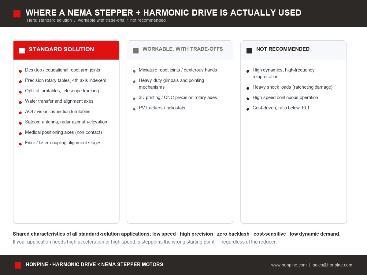
Where This Combination Is Actually Used
HONPINE Mini Harmonic Reducers for NEMA Motors
HONPINE mini harmonic reducers come in two configurations: SHD = hat type and CSF = cup type. Both are specified at 20 arcsec backlash, which is itself better than most "standard industrial grade" harmonic drives (3–6 arcmin) — the core advantage when pairing with NEMA motors is that backlash does not become the accuracy bottleneck of the complete machine.
SHD and CSF specifications
Rated torque at 2,000 rpm input, in N·m. Values shown as 30 / 50 / 80–100–120 ratio columns.
Input and output codes
Three points to confirm before quoting
Whether a NEMA adapter flange is a standard accessory. The 2XH input inserts the motor shaft directly, but whether the motor flange side is supplied with a standard NEMA frame adapter needs confirmation — accessory or custom item?
The official recommended NEMA frame for each harmonic frame. The pairing table above is inferred from torque magnitude; HONPINE can provide the official per-frame adaptation table.
The per-model input-side no-load starting torque (drag torque) and its measurement definition. This is the input to check 4 and is not currently listed in the catalogue. Contact sales@honpine.com for the measured values.
Quick Reference
How to calculate (eight steps): interface → ratio → four-tier output torque → input-side starting torque → motor operating point (curve, not holding torque) → inertia and resonance → resolution and repeatability separately → life and heat.
Why the pairing is common: a harmonic drive removes three stepper weaknesses (coarse step angle, high-speed torque collapse, no precision transmission) and moves the motor's operating point into the low-speed, high-torque sweet spot. Commercially it is the best combination of high precision, low cost, and no tuning.
The largest risk: silent failure (lost steps with no error plus ratcheting damage that is permanent) → choose one, and do not skip it: a closed-loop stepper, or a safety factor of ≥1.5–2.
Where it is used: desktop and educational robot joints, precision rotary tables and 4th axes, optical and telescope turntables, wafer transfer and alignment, AOI turntables, antenna and radar tracking, medical positioning axes (non-contact), fibre-laser alignment — the shared characteristics are low speed, high precision, zero backlash, cost sensitivity, and low dynamic requirements.
Learn more or request the official NEMA adaptation table: Website: www.honpine.com | E-mail: sales@honpine.com
Sources, Confidence Levels and Disclaimer
Disclaimer
1. HONPINE parameters are taken from the manufacturer's catalogue and are specification-level; the catalogue does not list input-side no-load starting torque or an official NEMA adaptation table, so the pairing suggestions here are inferences and must be confirmed in writing before use.
2. NEMA frame dimensions and holding torques are industry-typical values that differ between manufacturers; final design must follow the specification sheet of the target motor.
3. This article flags one conflict in public definitions (whether drag torque should be multiplied by the reduction ratio) and does not default to either; that parameter directly determines the matching conclusion, so its definition must be clarified with the manufacturer before use.
4. Conclusions involving certification, compliance, and safety levels are subject to official announcements and professional bodies; this article is not a basis for certification.
Published by HONPINE · Harmonic Drive × NEMA Stepper Motor Matching Series
Read More
Learn more about the story of HONPINE and industry trends related to precision transmission.
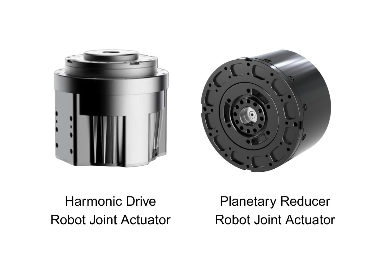
 What is robot joint actuator?How to Choose the Best Robot Rotary Joint Actuator?In core robot joint transmission solutions, planetary and harmonic rotary actuators each have their own strengths. Choosing the right type based on application requirements is essential to achieve the optimal balance between performance and cost.
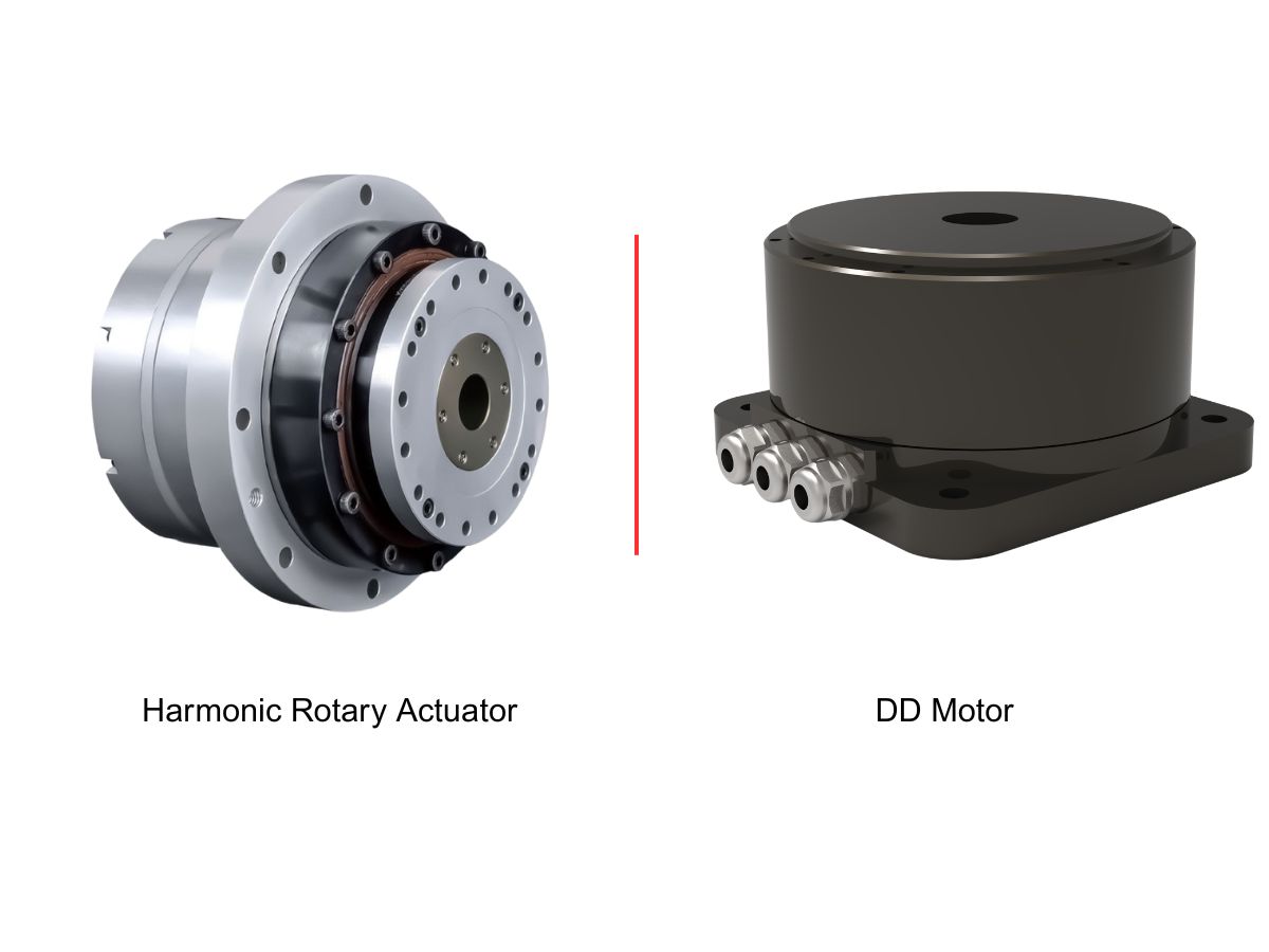
 DD Motors VS Harmonic Rotary ActuatorsThis article provides an in-depth comparison between Direct Drive (DD) motors and harmonic rotary actuators, covering their transmission principles, advantages and disadvantages, and typical application fields.
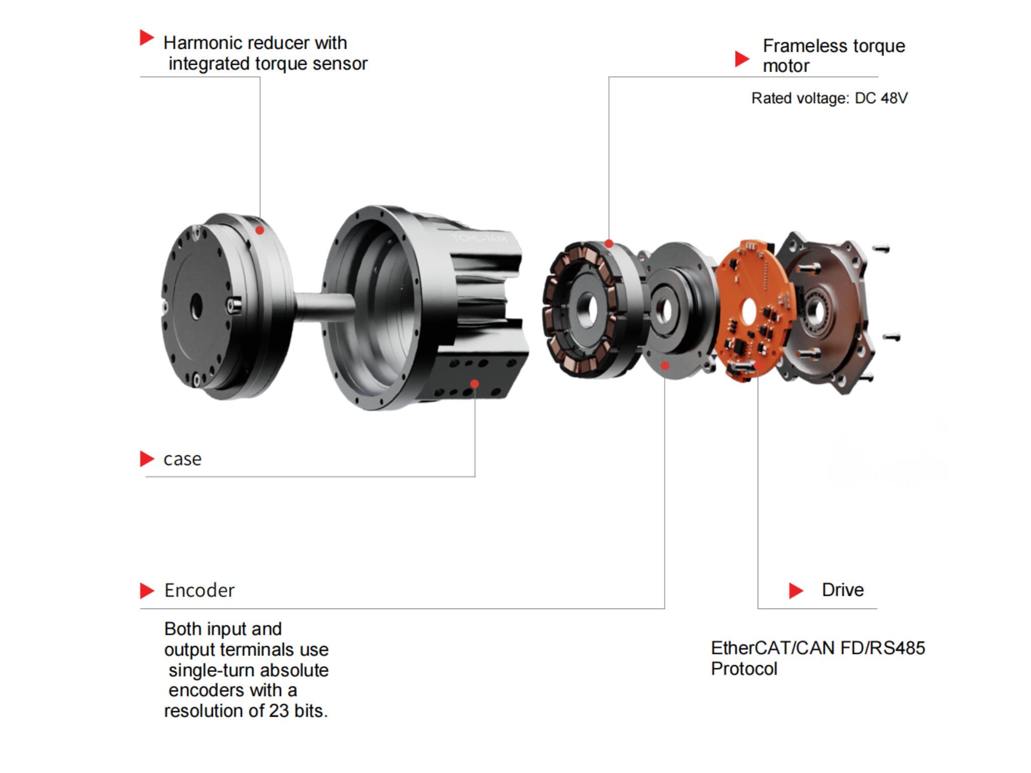
 OMG Ultra Compact Harmonic Drive Joint Module with Built-in Torque SensorHONPINE TCHL series harmonic drive joint module is a game-changing product that achieves disruptive improvements in multiple aspects such as lightweight design, integration level, and connection convenience. This article will analyze its revolutionary enhancements with you.
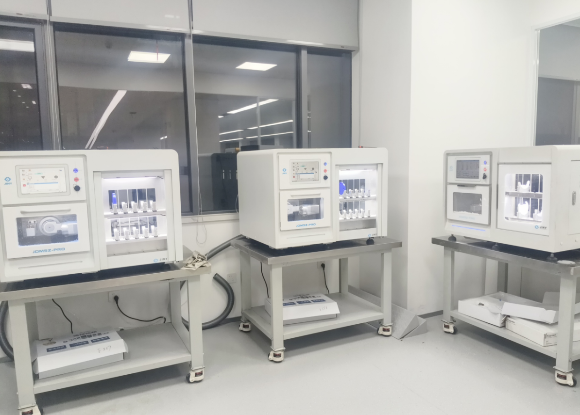
 The Role of Harmonic Drive Gears in Achieving 5–10 μm Accuracy in Dental Milling MachinesA dental milling machine is a CNC machining system used to directly process digital dental models into restorations such as crowns, bridges, veneers, inlays, and implant abutments. Dental milling machines require far higher operational accuracy and motion stability than ordinary equipment. This article explains how harmonic drive gear help dental milling machines achieve stable, continuous, and controllable operation.
 Why Are Harmonic Rotary Actuators Perfect for Medical Equipment?Harmonic rotary actuators (typically integrated systems consisting of a harmonic drive reducer, frameless torque motor, encoder, and optional brake) are regarded as key components in medical equipment. The core reason is that they simultaneously meet the most stringent medical requirements for precision, compact size, safety, and controllability. The following explanation is structured from three perspectives: technical characteristics, application scenarios, and medical value.
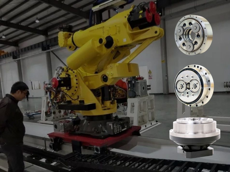
 High-Precision RV Reducers Perfectly Matched for Walking RobotsThe walking axis of a robot is a core component for power transmission and support. RV reducers provide extremely high rigidity, precision, and torque while maintaining a compact size and exceptional reliability, making them an ideal match for the demanding requirements of walking robot joints in terms of load capacity, impact resistance, and precision.
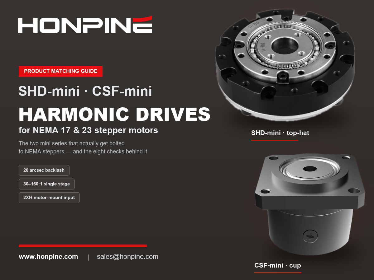
 NEMA 17 & NEMA 23 Harmonic Drive Matching Guide: Pairing Stepper Motors with Harmonic ReducersPairing a stepper motor with a harmonic drive is not a budget compromise. A stepper's weak points — the coarse step angle, torque collapse above roughly 400 rpm, and the lack of a precision transmission — are exactly what a harmonic drive fixes: it pulls the operating point into the low-speed, high-torque sweet spot, refines a 1.8° step angle into arc-second resolution, and delivers near-zero backlash. This guide explains what NEMA frame sizes mean at the mounting interface, which harmonic frames match NEMA 17 and NEMA 23, the eight checks to run in order — including the input-side no-load starting torque most often missed — and the pairing's real weakness: silent failure. Includes HONPINE SHD and CSF specifications.
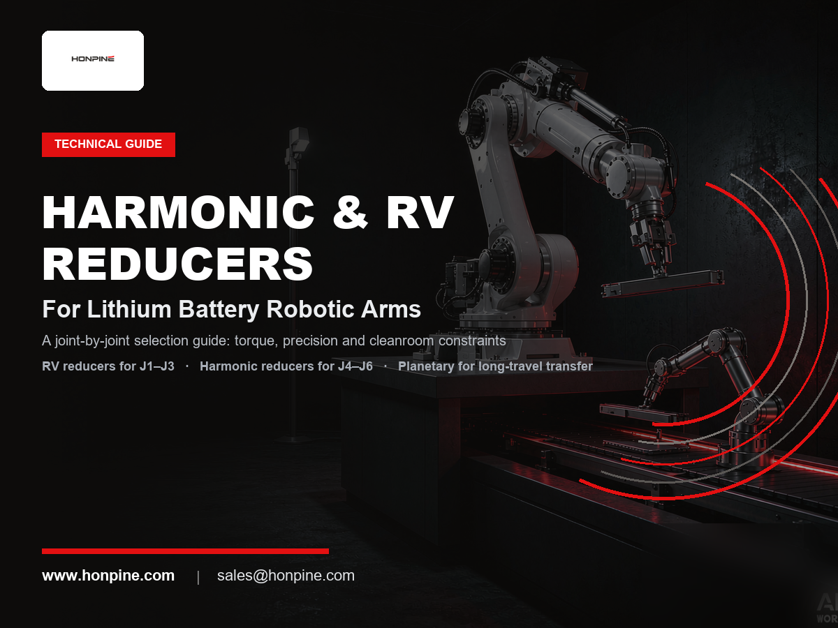
 Harmonic vs. RV Reducers for Lithium Battery Robotic Arms: A Joint-by-Joint Selection GuideIn lithium battery plants, reducer selection for a robotic arm is not about finding one "best" gearbox — it is about dividing work by joint. RV reducers take the shoulder and elbow (J1–J3), where stiffness, shock resistance, and long life matter most; harmonic reducers take the wrist (J4–J6), where near-zero backlash, high torque density, and low weight decide positioning accuracy. Planetary gearboxes cover long-travel Cartesian transfer at lower cost. Lithium battery production then adds three stricter filters: extreme repeatability (±0.02–0.05 mm), 24/7 high-duty cycles, and zero tolerance for metal particle contamination. This guide explains the logic behind joint-by-joint selection, compares the three reducer types, and maps typical configurations for every station.
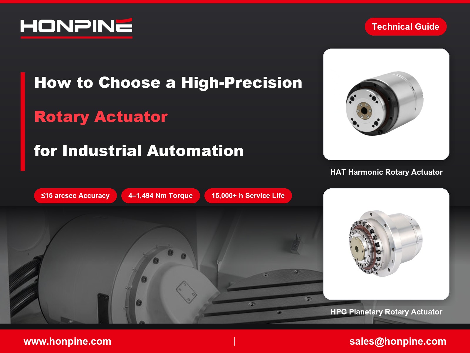
 How to Choose High-Precision Rotary Actuators for Industrial Automation?High-precision rotary actuators play an important role in industrial automation, where positioning accuracy, repeatability, durability and installation flexibility directly affect equipment performance. HONPINE offers four main series of precision rotary actuators, including HAT, HAM and HAS harmonic rotary actuators and HPG low-backlash planetary actuators. With torque ratings ranging from 4 to 1,494 Nm across the product range, these solutions are designed for applications in semiconductor manufacturing, 3C automation, laser processing and CNC machine tools. Learn how to identify the right rotary actuator based on operating conditions, precision requirements and mechanical integration needs.
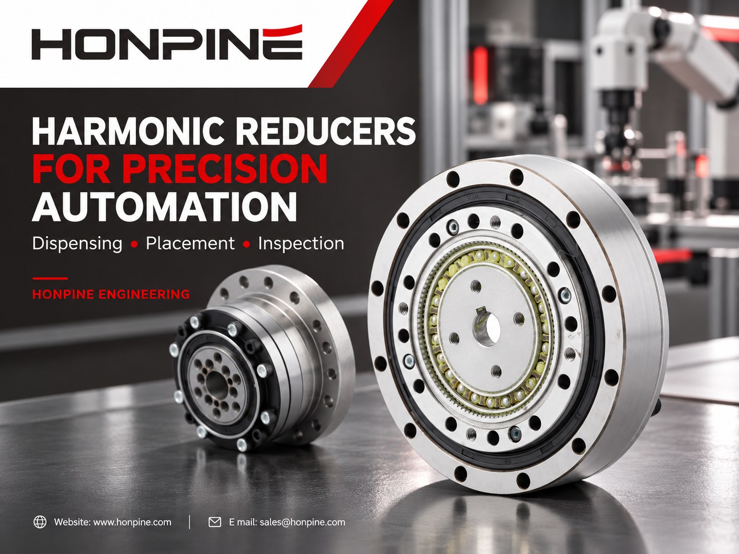
 Why Are Harmonic Reducers Suitable for High-Precision Automation Equipment?Precision automation equipment depends on consistent rotary motion, reliable positioning and compact transmission design. From dispensing head orientation and component angular alignment to automated inspection indexing, harmonic reducers offer a practical solution for applications requiring low backlash and high reduction ratios in limited installation space. This article explains how harmonic reducers support repeatable motion, compares key design configurations, and outlines how to select a suitable reduction ratio and reducer structure based on load, speed, accuracy and machine cycle-time requirements.
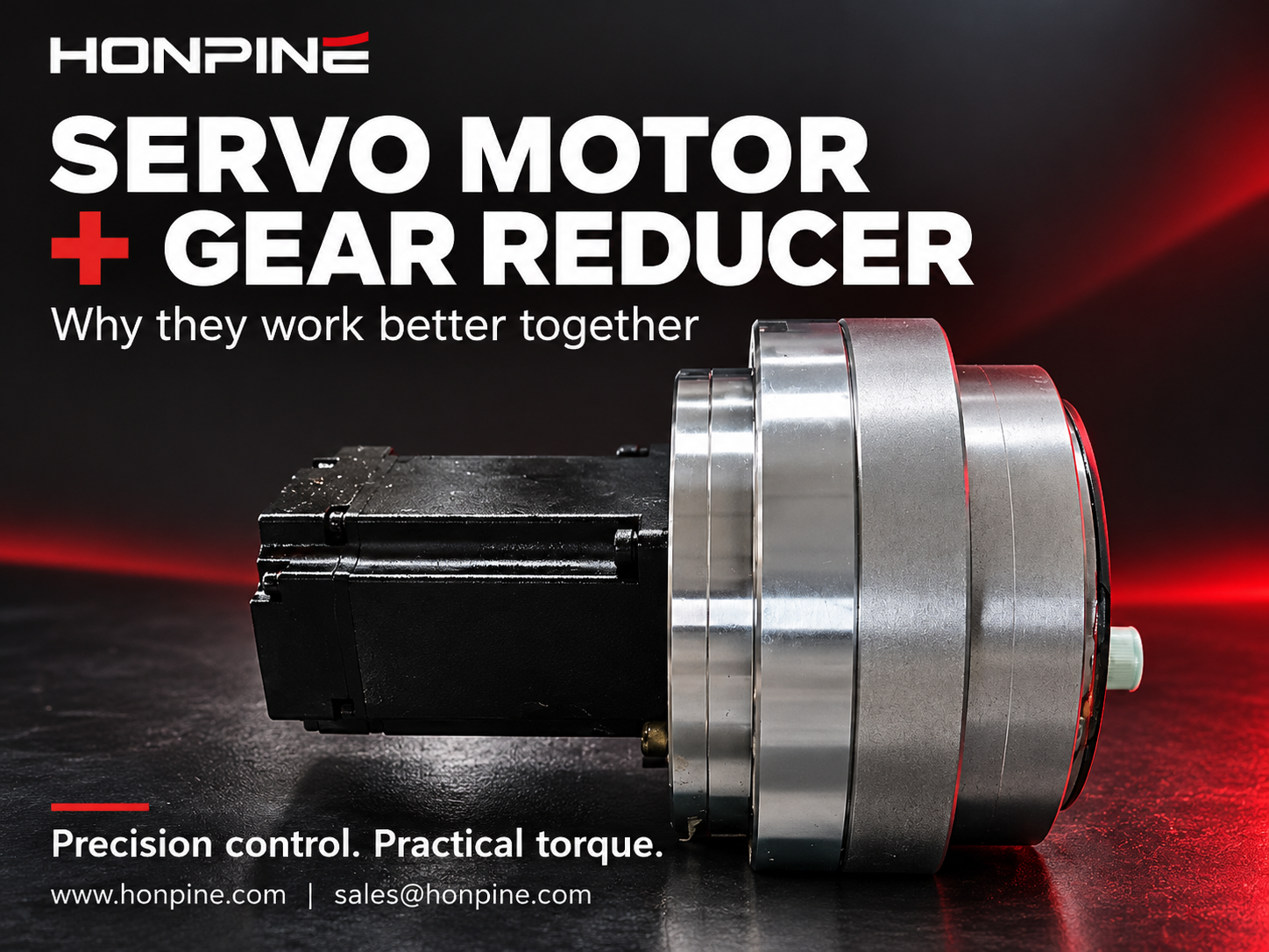
 Why Are Servo Motors and Gear Reducers an Ideal Match?Servo motors provide fast, precise motion control, while gear reducers adapt their speed and torque to the load. This guide explains how servo motors and gear reducers work together through torque multiplication, reflected inertia reduction and finer theoretical position resolution. Learn how inertia matching, backlash, torsional stiffness and reduction ratio influence performance in robotics and industrial automation.
 How to Select and Use Robotic Joint Modules?How do you take robotic joint modules from selection to controlled motion? Using the HONPINE HPJM harmonic joint module as an example, Technical Director Theodore Li explains the key steps in mechanical installation, electrical wiring, CAN and EtherCAT configuration, and control commissioning. Learn what to confirm before integration and how to approach setup so each joint can respond correctly to your controller.
Double Click
We provide harmonic drive reducer,planetary reducer,robot joint motor,robot rotary actuators,RV gear reducer,robot end effector,dexterous robot hand
 What is robot joint actuator?How to Choose the Best Robot Rotary Joint Actuator?In core robot joint transmission solutions, planetary and harmonic rotary actuators each have their own strengths. Choosing the right type based on application requirements is essential to achieve the optimal balance between performance and cost.
 DD Motors VS Harmonic Rotary ActuatorsThis article provides an in-depth comparison between Direct Drive (DD) motors and harmonic rotary actuators, covering their transmission principles, advantages and disadvantages, and typical application fields.
 OMG Ultra Compact Harmonic Drive Joint Module with Built-in Torque SensorHONPINE TCHL series harmonic drive joint module is a game-changing product that achieves disruptive improvements in multiple aspects such as lightweight design, integration level, and connection convenience. This article will analyze its revolutionary enhancements with you.
 NEMA 17 & NEMA 23 Harmonic Drive Matching Guide: Pairing Stepper Motors with Harmonic ReducersPairing a stepper motor with a harmonic drive is not a budget compromise. A stepper's weak points — the coarse step angle, torque collapse above roughly 400 rpm, and the lack of a precision transmission — are exactly what a harmonic drive fixes: it pulls the operating point into the low-speed, high-torque sweet spot, refines a 1.8° step angle into arc-second resolution, and delivers near-zero backlash. This guide explains what NEMA frame sizes mean at the mounting interface, which harmonic frames match NEMA 17 and NEMA 23, the eight checks to run in order — including the input-side no-load starting torque most often missed — and the pairing's real weakness: silent failure. Includes HONPINE SHD and CSF specifications.
 Harmonic vs. RV Reducers for Lithium Battery Robotic Arms: A Joint-by-Joint Selection GuideIn lithium battery plants, reducer selection for a robotic arm is not about finding one "best" gearbox — it is about dividing work by joint. RV reducers take the shoulder and elbow (J1–J3), where stiffness, shock resistance, and long life matter most; harmonic reducers take the wrist (J4–J6), where near-zero backlash, high torque density, and low weight decide positioning accuracy. Planetary gearboxes cover long-travel Cartesian transfer at lower cost. Lithium battery production then adds three stricter filters: extreme repeatability (±0.02–0.05 mm), 24/7 high-duty cycles, and zero tolerance for metal particle contamination. This guide explains the logic behind joint-by-joint selection, compares the three reducer types, and maps typical configurations for every station.
 How to Choose High-Precision Rotary Actuators for Industrial Automation?High-precision rotary actuators play an important role in industrial automation, where positioning accuracy, repeatability, durability and installation flexibility directly affect equipment performance. HONPINE offers four main series of precision rotary actuators, including HAT, HAM and HAS harmonic rotary actuators and HPG low-backlash planetary actuators. With torque ratings ranging from 4 to 1,494 Nm across the product range, these solutions are designed for applications in semiconductor manufacturing, 3C automation, laser processing and CNC machine tools. Learn how to identify the right rotary actuator based on operating conditions, precision requirements and mechanical integration needs.
 Why Are Harmonic Reducers Suitable for High-Precision Automation Equipment?Precision automation equipment depends on consistent rotary motion, reliable positioning and compact transmission design. From dispensing head orientation and component angular alignment to automated inspection indexing, harmonic reducers offer a practical solution for applications requiring low backlash and high reduction ratios in limited installation space. This article explains how harmonic reducers support repeatable motion, compares key design configurations, and outlines how to select a suitable reduction ratio and reducer structure based on load, speed, accuracy and machine cycle-time requirements.
 Why Are Servo Motors and Gear Reducers an Ideal Match?Servo motors provide fast, precise motion control, while gear reducers adapt their speed and torque to the load. This guide explains how servo motors and gear reducers work together through torque multiplication, reflected inertia reduction and finer theoretical position resolution. Learn how inertia matching, backlash, torsional stiffness and reduction ratio influence performance in robotics and industrial automation.
 How to Select and Use Robotic Joint Modules?How do you take robotic joint modules from selection to controlled motion? Using the HONPINE HPJM harmonic joint module as an example, Technical Director Theodore Li explains the key steps in mechanical installation, electrical wiring, CAN and EtherCAT configuration, and control commissioning. Learn what to confirm before integration and how to approach setup so each joint can respond correctly to your controller.
 How to Select Harmonic and RV Reducers for Each Axis of a Six-Axis Robot?What determines whether a six-axis robot joint needs a harmonic reducer or an RV reducer? The answer depends on torque, inertia, impact loads, bearing loads and installation space. This guide explains how to evaluate harmonic and RV reducers for the base, shoulder, elbow and wrist, with practical checks for stiffness, backlash and service life. Use the requirements of each axis to select a suitable reducer configuration.
 Top 7 RV Reducer Gearbox Manufacturers: Why Does Nabtesco Still Dominate?What sets RV reducer gearbox manufacturers apart, and why does Nabtesco remain a benchmark in this market? RV reducer production demands precise component machining, careful assembly and extensive engineering know-how. This article introduces seven manufacturers across RV reducers and related transmission technologies, examines the strengths behind Nabtesco's position, and explores HONPINE's development capabilities to help you understand the supplier landscape.
 How to Calculate Torque for a Harmonic Rotary Actuator in a Flipping Mechanism?How much torque does a harmonic rotary actuator need to flip a 10 kg load through 180 degrees? The answer depends on more than weight. Center-of-gravity offset, load inertia, acceleration and operating frequency all affect actuator selection. In this guide, Theodore Li, Technical Director at HONPINE, explains the calculation process using a horizontal-axis flipping example and outlines the checks needed for peak torque, continuous operation, output speed and bearing loads.