








DD Motor Servo System: How to Understand Mechanical Resonance and Solve Machine Vibration?
Introduction
In precision equipment driven by a DD motor, direct drive torque motor, or linear motor, engineers often encounter a frustrating commissioning problem: the machine vibrates during acceleration or constant-speed operation, abnormal noise appears, or the servo system becomes unstable even after repeated parameter adjustments.
In many cases, the root cause is not simply an incorrect servo gain setting.
The mechanical structure itself may have a resonance frequency that interacts with the servo control bandwidth.
This issue becomes particularly important in direct drive motion systems because a DD motor eliminates the conventional gearbox and mechanical transmission stages between the motor and the load. The motor directly drives the mechanical structure, which means the performance of the complete servo system becomes highly dependent on mechanical stiffness, moving mass, structural design, bearings, coupling conditions, and load characteristics.
For this reason, successful DD motor servo tuning requires engineers to consider both the servo controller and the mechanical system.
A servo system cannot compensate indefinitely for a mechanically weak or poorly designed structure.
What Is the ZERO CROSS Frequency in a DD Motor Servo System?
The ZERO CROSS point, commonly associated with the crossover frequency of the servo system, is an important reference when analyzing the relationship between servo control bandwidth and mechanical resonance.
For many DD motor applications, the velocity-loop crossover frequency is typically below approximately 100 Hz, although the actual value depends on the motor, load, mechanical structure, controller, and tuning strategy.
Linear motor systems can have even lower effective crossover frequencies in some applications.
The relative position between the servo crossover frequency and the mechanical resonance frequency therefore has a significant influence on system stability.
If a mechanical resonance occurs well within the controllable bandwidth of the servo system, the controller may be able to compensate for the disturbance effectively, depending on the system dynamics and available phase margin.
However, when a significant mechanical resonance occurs around or beyond the usable control bandwidth, simply increasing servo gain may not solve the problem. Instead, the additional gain can excite the resonance and cause oscillation, vibration, audible noise, or even servo instability.
Therefore, engineers should not evaluate a DD motor only by motor torque, encoder resolution, or positioning accuracy. The relationship between servo bandwidth and mechanical resonance is equally important.
Why Does Mechanical Resonance Cause DD Motor Vibration?
Mechanical resonance occurs when the excitation generated by the motor interacts with one or more natural frequencies of the mechanical structure.
A simplified mechanical model can be represented by a mass-spring system.
The natural frequency of the system depends primarily on the effective moving mass and structural stiffness. In a simplified form:
Natural Frequency ∝ √(Stiffness / Mass)
This relationship provides an important engineering insight.
Increasing structural stiffness generally raises the natural frequency, while increasing effective moving mass generally lowers it.
The same principle can be observed in a tuning fork. Its vibration characteristics are determined by its material, geometry, mass distribution, and structural stiffness.
A precision machine behaves in a similar way.
Once the mechanical structure, moving components, bearings, mounting interfaces, and load configuration are established, the machine naturally develops one or more dominant resonance frequencies.
This means that mechanical resonance is not simply a software problem.
Servo parameters can influence how strongly the system excites these frequencies, but the underlying natural frequency is fundamentally related to the mechanical structure.
The Relationship Between Mechanical Resonance and Servo Bandwidth
The key issue in DD motor tuning is not simply whether the machine has a resonance frequency.
Almost every real mechanical system has resonant modes.
The more important question is:
Where is the resonance frequency located relative to the servo control bandwidth?
Consider two simplified cases.
If the mechanical resonance is sufficiently separated from the effective servo bandwidth, the servo controller can normally operate without strongly exciting the resonance.
If the resonance is close to the servo crossover region, however, the controller may interact strongly with the mechanical mode. Increasing gain can then produce more vibration instead of better response.
This is why a machine that appears stable at low servo gain may begin vibrating immediately after an engineer increases the velocity gain or position gain.
The problem is not necessarily that the gain value is “wrong.”
The mechanical system may simply have reached a frequency range where the servo controller no longer has sufficient phase margin to suppress the resonance.
How Should Engineers Handle Different Mechanical Resonance Frequencies?
Not all resonance problems should be treated with the same servo tuning method.
The resonance frequency provides an important clue about which solution should be considered first.
Resonance Above 500 Hz: Digital Filtering Can Be Effective
High-frequency resonance, particularly resonance well above the primary servo bandwidth, is often easier to address through digital filtering.
For example, when a mechanical resonance occurs above approximately 500 Hz, a servo drive's digital notch filter or related resonance suppression function may be effective.
At these higher frequencies, the velocity loop generally does not need to maintain strong control authority comparable to the low-frequency region. A properly configured digital filter can therefore reduce the influence of the resonance while preserving the required low-frequency servo response.
However, the exact filter frequency, bandwidth, depth, and number of filters should be determined through actual frequency-response measurements rather than by applying a fixed value to every machine.
An excessively aggressive filter can introduce unnecessary phase lag or reduce system responsiveness.
Therefore, high-frequency filtering should still be performed as part of a structured servo tuning process.
Resonance Below 100 Hz: The Real Servo Tuning Challenge
Low-frequency resonance below approximately 100 Hz is much more difficult.
This frequency range overlaps with the core operating bandwidth of many servo systems. Applying a strong filter directly in this region can interfere with the velocity loop and reduce phase margin.
The result can be a system that appears to suppress one vibration mode while simultaneously becoming slower or less stable.
For this reason, low-frequency mechanical resonance should generally be investigated from the mechanical side first.
Instead of continuously modifying servo parameters, engineers should determine why the mechanical structure has such a low natural frequency.
Potential causes include insufficient structural stiffness, excessive moving mass, flexible mounting interfaces, bearing compliance, long unsupported structures, or inadequate mechanical connections.
In these cases, changing the servo gain may only move the problem rather than solve it.
Why Low-Frequency Resonance Should Be Solved Through Mechanical Design?
This is one of the most important principles when commissioning a DD motor servo system.
A servo controller can compensate for certain mechanical characteristics, but its ability to compensate is limited.
When the mechanical structure has a low natural frequency close to the servo crossover frequency, the controller must operate within a difficult dynamic environment.
If the engineer continuously reduces gain to prevent oscillation, the system may become stable but slow.
If the engineer increases gain to improve response, the mechanical resonance may be excited and machine vibration may increase.
This creates a common tuning dilemma:
Low gain provides stability but insufficient response; high gain provides faster response but excites mechanical resonance.
When this occurs, the correct solution may not be another round of parameter tuning.
The mechanical structure itself may need to be redesigned.
How Mechanical Structure Determines DD Motor Servo Performance?
A DD motor directly transmits torque to the load, so the mechanical interface becomes an important part of the servo system.
Several mechanical factors can influence the resonance characteristics of a direct drive system.
Structural Stiffness
Higher structural stiffness generally increases the natural frequency of the mechanical system and can create a larger separation between the mechanical resonance and the servo operating bandwidth.
For precision equipment, stiffness should therefore be considered during mechanical design rather than treated as an issue discovered during final commissioning.
Moving Mass
Increasing moving mass generally lowers the natural frequency.
This is especially important in direct drive rotary stages, linear stages, semiconductor equipment, inspection platforms, and precision automation systems where the motor may directly accelerate a large moving load.
Engineers should therefore evaluate not only the motor's rated torque but also the complete inertia and mass distribution of the moving system.
Bearing and Mounting Conditions
The bearing system and mounting interface can also influence system stiffness.
Even when the main structural frame is rigid, insufficient stiffness at the bearing support, motor mounting interface, or load connection can create an unexpected low-frequency mode.
This is why measuring the complete machine is often more useful than evaluating the motor alone.
Load Distribution and Structural Geometry
A long arm, cantilever structure, offset load, or uneven mass distribution can introduce additional vibration modes.
In robotic positioning systems, optical inspection equipment, wafer handling equipment, and precision rotary stages, these structural characteristics should be considered during the initial mechanical design.
Why Increasing Servo Gain Does Not Always Improve DD Motor Performance?
Higher servo gain is often associated with faster response and higher disturbance rejection.
However, higher gain does not automatically mean better machine performance.
If the mechanical system has a resonance near the control bandwidth, increasing gain can amplify the interaction between the servo controller and the mechanical structure.
Typical symptoms may include:
Machine vibration during acceleration and deceleration
Audible high-frequency noise
Oscillation around the target position
Positioning overshoot
Increased settling time
Servo following-error fluctuations
Instability after increasing velocity or position gain
These symptoms should not automatically be interpreted as a drive tuning problem.
The engineer should first determine whether a mechanical resonance is being excited.
This is particularly important for DD motor systems because the direct connection between the motor and load makes the mechanical structure an integral part of the motion-control system.
A Practical DD Motor Servo Tuning Strategy
A structured tuning process can help engineers avoid repeatedly changing parameters without understanding the underlying cause.
Step 1: Identify the Resonance Frequency
Before changing servo gains, identify the dominant resonance frequencies of the machine.
Frequency-response analysis, servo drive diagnostic functions, vibration measurements, or other appropriate measurement methods can help locate the resonance.
The objective is to understand whether the dominant mechanical mode is located at a low, medium, or high frequency.
Step 2: Compare Resonance Frequency with Servo Crossover Frequency
Once the resonance frequency is identified, compare it with the effective servo bandwidth.
If the resonance is far above the main control bandwidth, digital filtering may be an appropriate solution.
If the resonance is close to or below the servo crossover region, mechanical optimization should receive greater attention.
Step 3: Apply Filtering Only When Appropriate
For high-frequency resonance, a notch filter or digital resonance suppression function can often provide an efficient solution.
The filter should be configured according to the measured resonance frequency.
Engineers should avoid applying excessive filtering because unnecessary filtering can reduce phase margin and dynamic response.
Step 4: Reevaluate the Mechanical Structure for Low-Frequency Resonance
When the resonance frequency is very low, the mechanical structure should be investigated.
Possible improvements include increasing structural stiffness, reducing unnecessary moving mass, shortening unsupported structures, improving bearing support, strengthening mounting interfaces, and optimizing the load path.
The objective is not simply to eliminate vibration through software.
The objective is to move the mechanical resonance to a frequency range where the servo system can control the machine more effectively.
Step 5: Retune the Servo System
After the mechanical structure has been optimized, servo parameters should be adjusted again.
A mechanically improved system generally provides a better foundation for increasing control bandwidth and achieving faster settling time without excessive vibration.
This is why mechanical design and servo tuning should not be treated as completely separate engineering tasks.
DD Motor vs Linear Motor: Why Resonance Can Be a Common Challenge
DD motors and linear motors use different mechanical arrangements, but both can be highly sensitive to the dynamic characteristics of the machine structure.
A DD motor directly generates rotary motion at the load, while a linear motor directly generates linear force.
Because both technologies minimize conventional mechanical transmission components, the motor can respond directly to the mechanical load.
This provides significant advantages for precision positioning, including low mechanical transmission error, high responsiveness, and reduced backlash-related effects.
However, it also means that mechanical stiffness, load inertia, mounting conditions, and structural resonance can have a strong influence on the overall servo system.
Therefore, both DD motor systems and linear motor systems require close coordination between mechanical design and servo control.
Why Direct Drive Systems Require Mechanical and Servo Co-Design?
One of the major advantages of a direct drive system is the reduction of mechanical transmission components.
There is no conventional gearbox between the motor and load, which can simplify the transmission chain and improve motion responsiveness.
However, removing the transmission does not remove mechanical dynamics.
Instead, the direct drive motor becomes more directly coupled to the mechanical structure.
This makes system-level engineering particularly important.
The motor, encoder, bearing, load, machine frame, mounting interface, controller, and servo parameters should be considered as one motion-control system.
For high-precision equipment, achieving the best performance therefore requires both:
A mechanically rigid and dynamically well-designed structure
and
A servo system with sufficient bandwidth and appropriate resonance suppression.
Neither side can fully compensate for the shortcomings of the other.
Where Mechanical Resonance Control Is Especially Important?
Mechanical resonance management is particularly important in applications where high positioning accuracy and short settling time are required.
These include precision CNC rotary axes, semiconductor manufacturing equipment, wafer handling systems, optical inspection equipment, AOI systems, laser processing equipment, precision rotary stages, industrial automation systems, and advanced robotic mechanisms.
In these applications, machine vibration does not only affect acoustic noise.
It can directly influence positioning accuracy, settling time, inspection repeatability, surface quality, image stability, machining quality, and production throughput.
For example, vibration in an optical inspection stage can affect image acquisition, while vibration in a CNC rotary axis can influence machining accuracy and surface finish.
The higher the required positioning accuracy and dynamic response, the more important mechanical resonance becomes.
How HONPINE Direct Drive Torque Motors Support Precision Motion Systems?
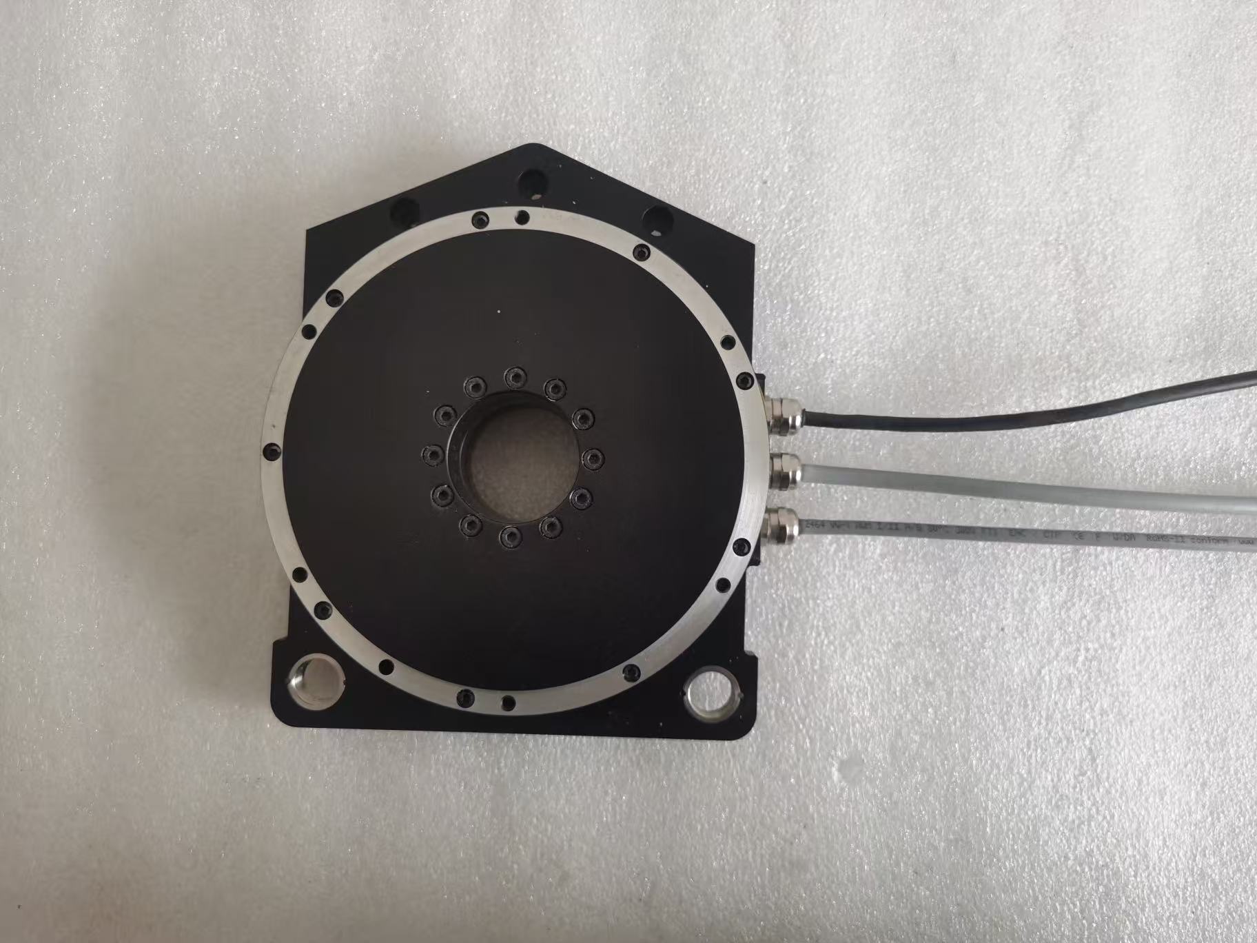
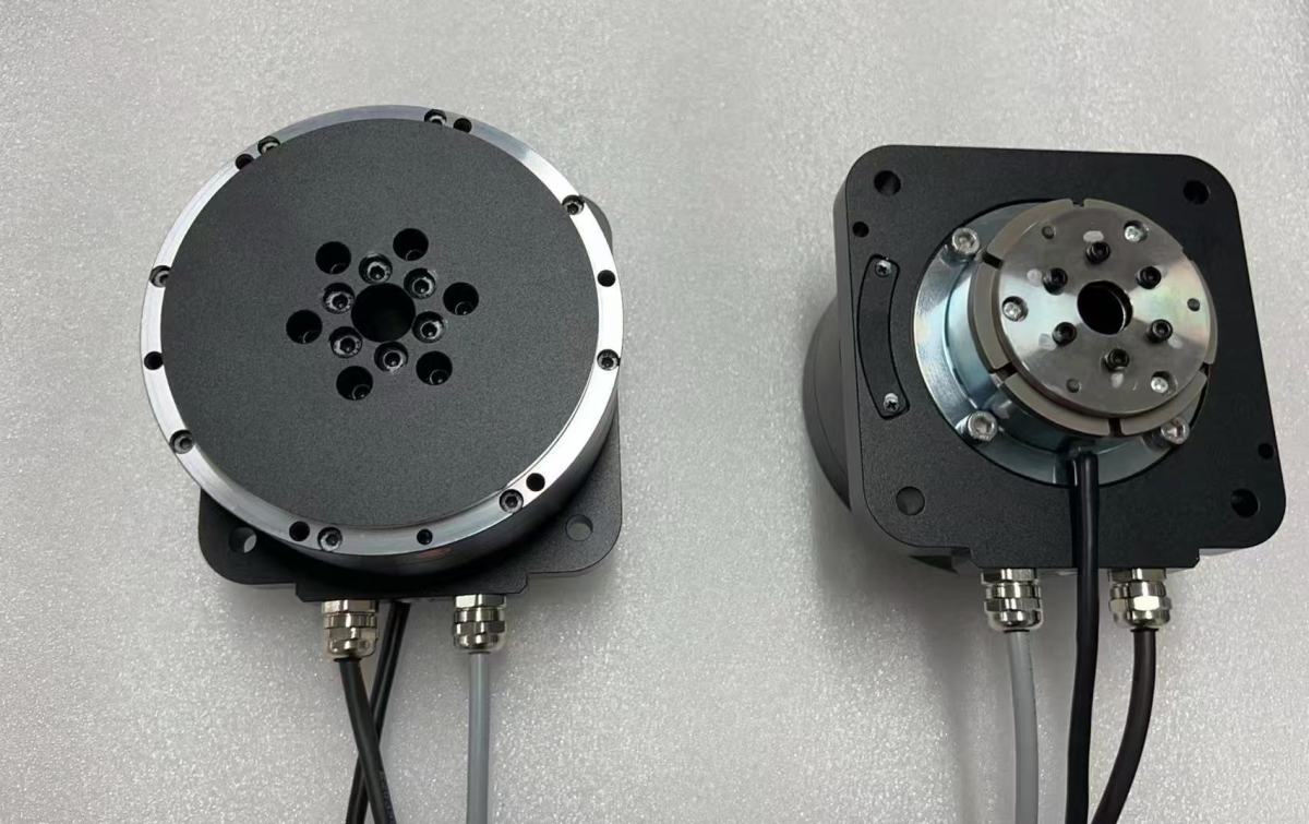
As a manufacturer of precision motion components, HONPINE develops direct drive torque motors and DD motor solutions for applications where high positioning accuracy, direct torque transmission, compact integration, and dynamic response are important.
However, the performance of a DD motor cannot be evaluated independently from the machine structure.
When selecting a direct drive torque motor, engineers should consider motor torque, continuous torque, peak torque, rotor inertia, encoder resolution, load inertia, structural stiffness, bearing configuration, and required servo bandwidth together.
HONPINE can evaluate the motor and application requirements from a system perspective, helping equipment manufacturers match the direct drive motor with the mechanical load and motion requirements.
For precision automation, CNC, semiconductor equipment, optical inspection, robotics, and other demanding motion applications, this system-level approach can help engineers achieve a better balance between torque, accuracy, dynamic response, and vibration control.
Conclusion: Solve the Mechanical Resonance, Not Just the Servo Parameter
Mechanical resonance is one of the most common reasons why a high-performance DD motor servo system fails to deliver the expected machine performance.
The key is to understand the relationship between mechanical resonance frequency and servo crossover frequency.
For high-frequency resonance, digital filtering can often provide an effective solution when properly configured.
For low-frequency resonance, especially when the resonance approaches or overlaps with the servo control bandwidth, mechanical optimization should generally take priority.
The most important principle is simple:
Do not expect servo parameters to compensate indefinitely for an insufficiently rigid mechanical structure.
A high-performance direct drive system requires both a well-designed mechanical structure and a properly tuned servo system.
By analyzing mass, stiffness, resonance frequency, servo bandwidth, filtering, and load characteristics together, engineers can move beyond trial-and-error tuning and build a more stable, responsive, and precise motion system.
For equipment manufacturers developing precision automation, CNC, semiconductor, inspection, robotics, and other advanced motion systems, choosing the right DD motor or direct drive torque motor is only the beginning. The ultimate performance comes from matching the motor, mechanical structure, encoder, controller, and servo parameters as one integrated system.
Read More
Learn more about the story of HONPINE and industry trends related to precision transmission.
 What is robot joint actuator?How to Choose the Best Robot Rotary Joint Actuator?In core robot joint transmission solutions, planetary and harmonic rotary actuators each have their own strengths. Choosing the right type based on application requirements is essential to achieve the optimal balance between performance and cost.
 DD Motors VS Harmonic Rotary ActuatorsThis article provides an in-depth comparison between Direct Drive (DD) motors and harmonic rotary actuators, covering their transmission principles, advantages and disadvantages, and typical application fields.
 OMG Ultra Compact Harmonic Drive Joint Module with Built-in Torque SensorHONPINE TCHL series harmonic drive joint module is a game-changing product that achieves disruptive improvements in multiple aspects such as lightweight design, integration level, and connection convenience. This article will analyze its revolutionary enhancements with you.
 The Role of Harmonic Drive Gears in Achieving 5–10 μm Accuracy in Dental Milling MachinesA dental milling machine is a CNC machining system used to directly process digital dental models into restorations such as crowns, bridges, veneers, inlays, and implant abutments. Dental milling machines require far higher operational accuracy and motion stability than ordinary equipment. This article explains how harmonic drive gear help dental milling machines achieve stable, continuous, and controllable operation.
 Why Are Harmonic Rotary Actuators Perfect for Medical Equipment?Harmonic rotary actuators (typically integrated systems consisting of a harmonic drive reducer, frameless torque motor, encoder, and optional brake) are regarded as key components in medical equipment. The core reason is that they simultaneously meet the most stringent medical requirements for precision, compact size, safety, and controllability. The following explanation is structured from three perspectives: technical characteristics, application scenarios, and medical value.
 High-Precision RV Reducers Perfectly Matched for Walking RobotsThe walking axis of a robot is a core component for power transmission and support. RV reducers provide extremely high rigidity, precision, and torque while maintaining a compact size and exceptional reliability, making them an ideal match for the demanding requirements of walking robot joints in terms of load capacity, impact resistance, and precision.
 DD Motor Servo System: How to Understand Mechanical Resonance and Solve Machine Vibration?This article explains the relationship between DD motor servo tuning, mechanical resonance, and servo bandwidth in direct drive motion systems. It examines why vibration and instability can occur even after repeated servo parameter adjustments, and explains how mechanical stiffness, moving mass, bearing conditions, load distribution, and structural geometry affect resonance frequency. The article also compares approaches for high- and low-frequency resonance, explains when digital notch filtering can be effective, and provides a practical tuning strategy for engineers working with DD motors, direct drive torque motors, and linear motors.
 High Precision Harmonic Drive Robot Joint Actuator Solution for Robotic ElbowsThe robotic elbow joint plays a critical role in arm flexion, posture adjustment, and end-effector positioning. As humanoid robots, collaborative robots, and robotic arms become more capable, elbow actuators need to deliver high torque and precise motion within increasingly limited installation spaces. A high precision harmonic drive robot joint actuator integrates the harmonic reducer, motor, encoder, brake, and drive system into a compact unit, providing low backlash, high stiffness, high torque density, and accurate motion control. In this article, HONPINE introduces three joint actuator series suitable for robotic elbow applications, covering different requirements for size, torque, speed, precision, and integration.
 Explosion-Proof Robot Joint Solution for Chemical Inspection Quadruped Robots: Planetary Joint Actuator with Up to 500 N·m Peak TorqueIn petrochemical, mining, power, and other hazardous environments, inspection robots are moving beyond simple monitoring toward practical operations such as tool handling, equipment inspection, and emergency response. This shift places higher demands on robot joint actuators, particularly in explosion protection, torque output, thermal management, environmental resistance, and mobility. HONPINE's explosion-proof robot joint actuator is designed for quadruped inspection robots and other hazardous-environment robotic platforms, integrating high-load planetary transmission with explosion-proof design and reliable motion performance. With up to 500 N·m peak torque per joint, optional IP67 protection, and Ex db IIB T4 Gb certification, the solution is designed to support demanding robotic applications in high-risk industrial environments.
 Planetary Drive Actuator for AGV Wheel Hub Motors: Solving Torque, Turning Radius and Drive Integration ChallengesHello everyone, I’m Theodore Li, Technical Director at HONPINE. Today, I’d like to discuss how a planetary drive actuator can solve practical challenges in AGV wheel hub motor systems. AGVs and AMRs require sufficient wheel torque for heavy-load starting, acceleration, slope climbing, and frequent reversing, while the drive system must remain compact enough for limited chassis space. A planetary drive actuator combines a motor with a planetary reduction mechanism to convert high-speed motor output into the lower-speed, higher-torque motion required at the wheel. In this article, I will examine the relationship between planetary drive actuators and AGV wheel hub motors, including torque, gear ratio, wheel diameter, climbing ability, turning radius, direct-drive systems, and harmonic drive actuators.
 How to Choose a Reliable Robot Joint Motor Manufacturer for Humanoid Robots?Choosing a reliable robot joint motor manufacturer is a critical step when developing humanoid robots and other advanced robotic systems. A robotic joint must balance torque, speed, precision, torque density, thermal performance, feedback, mechanical stiffness, and long-term reliability within a compact structure. For B2B robotics companies, supplier evaluation should therefore go beyond a product datasheet and consider engineering capability, manufacturing capacity, joint integration, testing, and production scalability. In this article, Allen Li, Founder of HONPINE, explains the key factors to consider when selecting a robot joint motor manufacturer and how integrated harmonic robot joint technology can support humanoid robot development.
 Lightweight Humanoid Robots Start with Precision TransmissionAs humanoid robots move from experimental prototypes toward practical applications, lightweight design, energy efficiency, motion performance, and long-term reliability are becoming increasingly important. At the center of these challenges is precision transmission. From harmonic reducers and lightweight robot joints to integrated development kits, the design of each core component directly affects the overall performance of a humanoid robot. In this article, Allen Li, Founder of HONPINE, shares his perspective on how precision transmission technology can support the development of lightweight humanoid robots and how HONPINE is extending its expertise from harmonic reducers toward lightweight robot joints and integrated robotics solutions.
Double Click
We provide harmonic drive reducer,planetary reducer,robot joint motor,robot rotary actuators,RV gear reducer,robot end effector,dexterous robot hand
 What is robot joint actuator?How to Choose the Best Robot Rotary Joint Actuator?In core robot joint transmission solutions, planetary and harmonic rotary actuators each have their own strengths. Choosing the right type based on application requirements is essential to achieve the optimal balance between performance and cost.
 DD Motors VS Harmonic Rotary ActuatorsThis article provides an in-depth comparison between Direct Drive (DD) motors and harmonic rotary actuators, covering their transmission principles, advantages and disadvantages, and typical application fields.
 OMG Ultra Compact Harmonic Drive Joint Module with Built-in Torque SensorHONPINE TCHL series harmonic drive joint module is a game-changing product that achieves disruptive improvements in multiple aspects such as lightweight design, integration level, and connection convenience. This article will analyze its revolutionary enhancements with you.
 DD Motor Servo System: How to Understand Mechanical Resonance and Solve Machine Vibration?This article explains the relationship between DD motor servo tuning, mechanical resonance, and servo bandwidth in direct drive motion systems. It examines why vibration and instability can occur even after repeated servo parameter adjustments, and explains how mechanical stiffness, moving mass, bearing conditions, load distribution, and structural geometry affect resonance frequency. The article also compares approaches for high- and low-frequency resonance, explains when digital notch filtering can be effective, and provides a practical tuning strategy for engineers working with DD motors, direct drive torque motors, and linear motors.
 High Precision Harmonic Drive Robot Joint Actuator Solution for Robotic ElbowsThe robotic elbow joint plays a critical role in arm flexion, posture adjustment, and end-effector positioning. As humanoid robots, collaborative robots, and robotic arms become more capable, elbow actuators need to deliver high torque and precise motion within increasingly limited installation spaces. A high precision harmonic drive robot joint actuator integrates the harmonic reducer, motor, encoder, brake, and drive system into a compact unit, providing low backlash, high stiffness, high torque density, and accurate motion control. In this article, HONPINE introduces three joint actuator series suitable for robotic elbow applications, covering different requirements for size, torque, speed, precision, and integration.
 Explosion-Proof Robot Joint Solution for Chemical Inspection Quadruped Robots: Planetary Joint Actuator with Up to 500 N·m Peak TorqueIn petrochemical, mining, power, and other hazardous environments, inspection robots are moving beyond simple monitoring toward practical operations such as tool handling, equipment inspection, and emergency response. This shift places higher demands on robot joint actuators, particularly in explosion protection, torque output, thermal management, environmental resistance, and mobility. HONPINE's explosion-proof robot joint actuator is designed for quadruped inspection robots and other hazardous-environment robotic platforms, integrating high-load planetary transmission with explosion-proof design and reliable motion performance. With up to 500 N·m peak torque per joint, optional IP67 protection, and Ex db IIB T4 Gb certification, the solution is designed to support demanding robotic applications in high-risk industrial environments.
 Planetary Drive Actuator for AGV Wheel Hub Motors: Solving Torque, Turning Radius and Drive Integration ChallengesHello everyone, I’m Theodore Li, Technical Director at HONPINE. Today, I’d like to discuss how a planetary drive actuator can solve practical challenges in AGV wheel hub motor systems. AGVs and AMRs require sufficient wheel torque for heavy-load starting, acceleration, slope climbing, and frequent reversing, while the drive system must remain compact enough for limited chassis space. A planetary drive actuator combines a motor with a planetary reduction mechanism to convert high-speed motor output into the lower-speed, higher-torque motion required at the wheel. In this article, I will examine the relationship between planetary drive actuators and AGV wheel hub motors, including torque, gear ratio, wheel diameter, climbing ability, turning radius, direct-drive systems, and harmonic drive actuators.
 How to Choose a Reliable Robot Joint Motor Manufacturer for Humanoid Robots?Choosing a reliable robot joint motor manufacturer is a critical step when developing humanoid robots and other advanced robotic systems. A robotic joint must balance torque, speed, precision, torque density, thermal performance, feedback, mechanical stiffness, and long-term reliability within a compact structure. For B2B robotics companies, supplier evaluation should therefore go beyond a product datasheet and consider engineering capability, manufacturing capacity, joint integration, testing, and production scalability. In this article, Allen Li, Founder of HONPINE, explains the key factors to consider when selecting a robot joint motor manufacturer and how integrated harmonic robot joint technology can support humanoid robot development.
 Lightweight Humanoid Robots Start with Precision TransmissionAs humanoid robots move from experimental prototypes toward practical applications, lightweight design, energy efficiency, motion performance, and long-term reliability are becoming increasingly important. At the center of these challenges is precision transmission. From harmonic reducers and lightweight robot joints to integrated development kits, the design of each core component directly affects the overall performance of a humanoid robot. In this article, Allen Li, Founder of HONPINE, shares his perspective on how precision transmission technology can support the development of lightweight humanoid robots and how HONPINE is extending its expertise from harmonic reducers toward lightweight robot joints and integrated robotics solutions.
 Hollow-Shaft Direct Drive Motor for Heavy-Duty Precision Positioning and Industrial AutomationIn heavy-duty automation, precision positioning depends not only on the motor but also on the mechanical transmission between the motor and the load. A hollow shaft direct drive motor delivers torque directly to the load while providing a central passage for cables, pneumatic lines and other components. This makes it a practical solution for CNC machining, photovoltaic, lithium battery, optical inspection and semiconductor equipment.
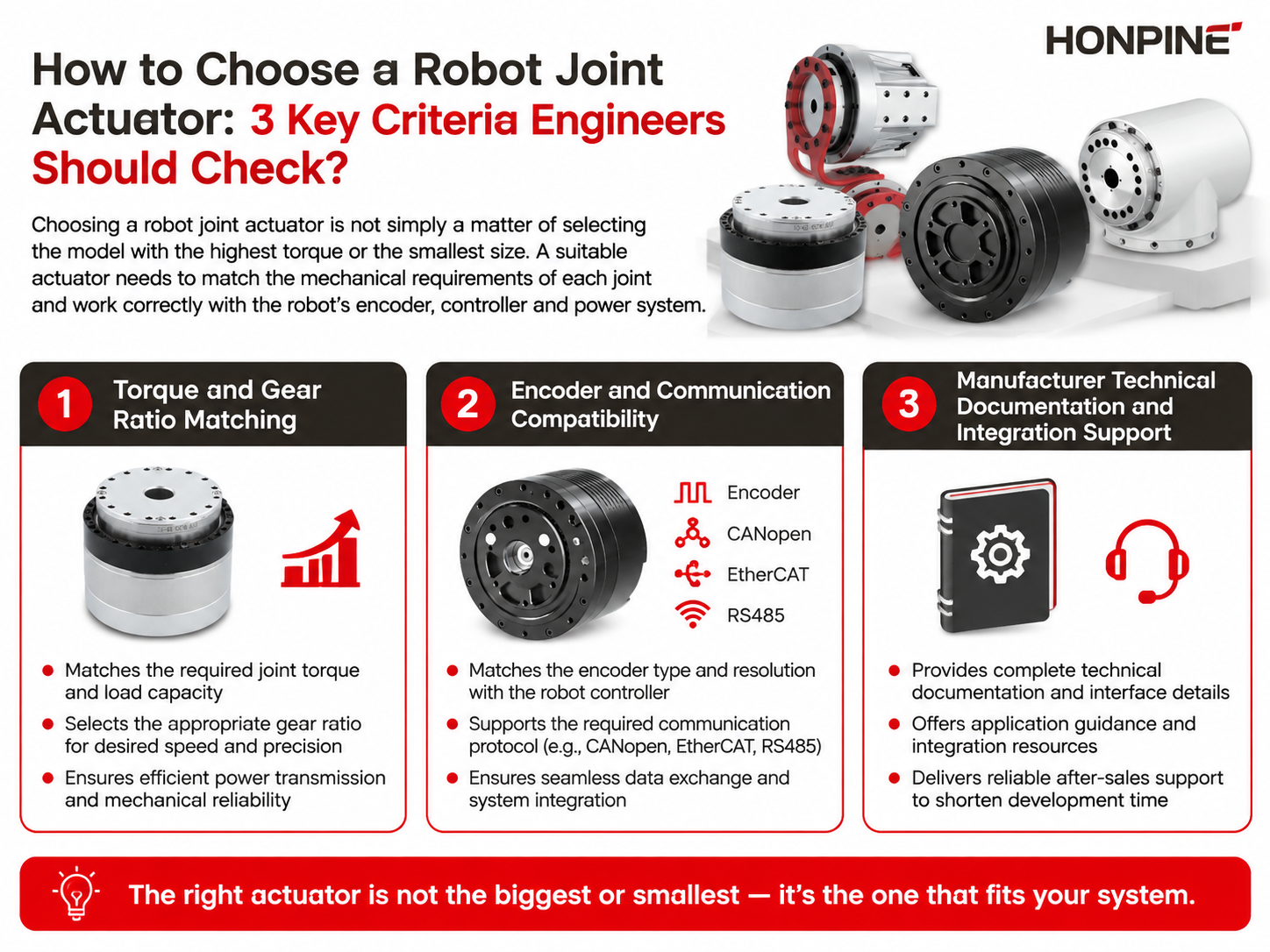
 How to Choose a Robot Joint Actuator: 3 Key Criteria Engineers Should Check?Choosing a robot joint actuator is an engineering decision that affects not only torque and motion performance, but also control stability, mechanical integration, and development time. For industrial robots, collaborative robots, humanoid robots, and other robotic systems, the right actuator must match the actual requirements of each joint while remaining compatible with the robot’s motor, encoder, controller, communication network, and power architecture. In this article, I will explain three key criteria engineers should evaluate when selecting a robot joint actuator: torque and gear ratio matching, encoder and communication compatibility, and the manufacturer’s technical documentation and engineering support.
 Outdoor Robot Joint Solution: Harmonic Joint Module with Built-in Torque SensorHello everyone, I’m Theodore Li, Technical Director at HONPINE. As robots move beyond controlled factory environments, outdoor robotic applications are creating new requirements for robot joint design. Rain, dust, humidity, temperature fluctuations, low-temperature conditions, and unpredictable external loads can all affect how a robotic joint performs in the field. In these environments, a joint needs to provide more than precise rotation. It also needs reliable torque feedback, suitable environmental protection, stable operation under changing temperatures, and practical mechanical integration. In this article, I will explain the key engineering considerations behind our outdoor robot joint solution, including the harmonic joint module, built-in torque sensor, IP65 protection, low-temperature lubrication, cable outlet protection, and mechanical integration, based on our experience with outdoor robotic applications such as solar panel installation, construction, and cleaning robots.