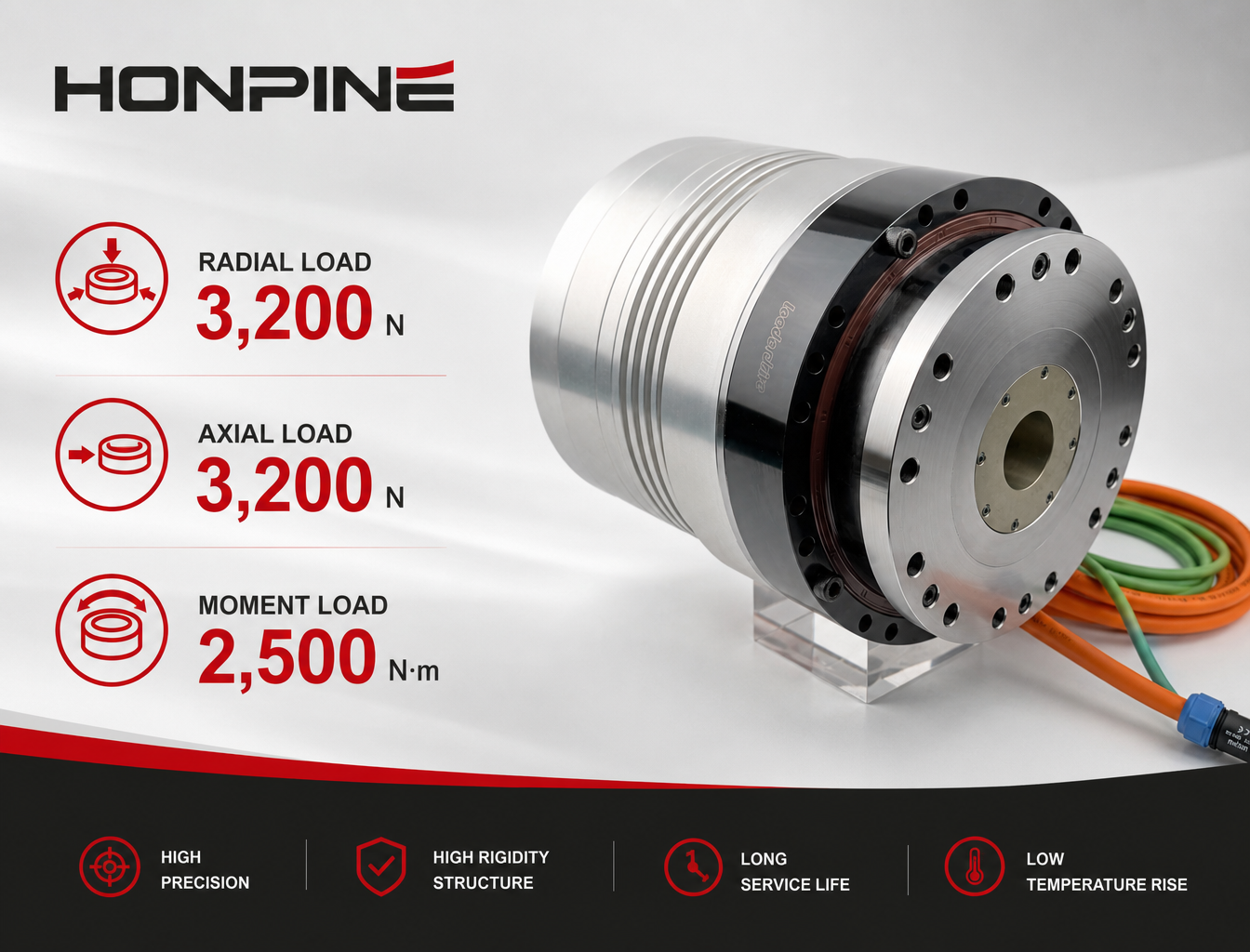









HPJM Harmonic Joint Actuator PID Tuning: How to Reduce Positioning Jitter
Positioning jitter can occur when a robot joint repeatedly oscillates around the commanded position or fails to settle smoothly after reaching the target. For a high-precision harmonic joint actuator, this behavior is often related to the interaction between PID parameters, load conditions, transmission characteristics, and the mechanical structure.
The HPJM Harmonic Joint Actuator provides a configurable PID interface that allows users to adjust the speed and position control parameters according to different loads and operating conditions. The current loop is calibrated before delivery, while the speed and position loops can be tuned by the user when necessary.
This article explains the PID control structure of the HPJM harmonic joint actuator, the role of the main PID parameters, and a practical procedure for reducing positioning jitter through CAN, CANopen, EtherCAT, or the Magic software.
Why Does Positioning Jitter Occur in a Robot Joint Actuator?
A robot joint does not operate as a motor alone. The complete motion system includes the motor, harmonic transmission, encoder, bearings, mechanical housing, load, and servo control system.
When the commanded position is reached, the controller continuously compares the target position with the actual position. If the control response is too aggressive for the mechanical characteristics of the joint, the actuator may repeatedly correct the position in opposite directions.
This can appear as:
Small oscillations around the target position
Repeated forward and reverse corrections
Audible or visible vibration
Longer settling time
Unstable motion under certain loads
Therefore, positioning jitter should not automatically be attributed to the harmonic reducer or encoder. In many cases, the PID parameters need to be matched to the actual load and mechanical conditions of the robot joint.
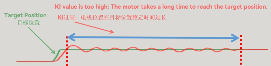
How PID Control Works in the HPJM Harmonic Joint Actuator?
PID control determines the control output according to the error between the commanded value and the actual system response.
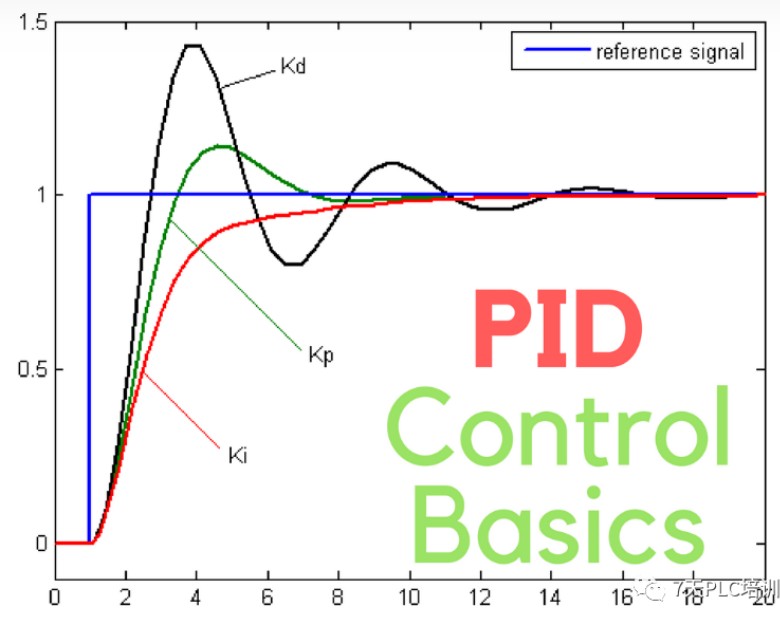
The three basic components are:
P — Proportional
The proportional term responds to the magnitude of the current error. Increasing proportional gain generally makes the control system respond more strongly to position or speed deviations.
I — Integral
The integral term accumulates error over time and is primarily used to reduce steady-state error or residual deviation.
D — Derivative
The derivative term responds to the rate of change of the error and can provide anticipatory damping during dynamic changes.
In the HPJM control architecture, the loops are arranged in a cascaded structure:
Current Loop → Speed Loop → Position Loop
The current loop is the innermost loop and directly controls motor current and electromagnetic torque. The speed loop controls motor speed, while the position loop controls the final position response.
The current-loop parameters are calibrated before delivery and should generally not be modified by the user.
For application-specific tuning, the main parameters to adjust are:
Speed Loop P → Speed Loop I → Position Loop P → Position Loop D
Why Should the PID Parameters Be Adjusted According to Load?
A harmonic joint actuator can be installed in different robotic applications with significantly different mechanical loads.
For example, the same HPJM actuator may experience different dynamic characteristics when installed in:
A robotic arm joint
A humanoid robot joint
A lightweight collaborative robot
A rotating head mechanism
A compact robotic manipulator
The load affects inertia, friction, acceleration response, and the mechanical resonance characteristics of the complete joint.
As a result, PID parameters that work well under one load condition may not provide the same positioning performance under another.
This is why PID tuning should be performed under the actual or representative operating load rather than using a single parameter set for every application.
How to Adjust the Position Loop of the HPJM Harmonic Joint Actuator?
The position loop has a direct influence on how the robot joint responds to position errors.
Position Loop P Gain
The position proportional gain determines how strongly the actuator responds to position error.
If the position P gain is too low, the actuator may respond slowly or exhibit insufficient positioning stiffness.
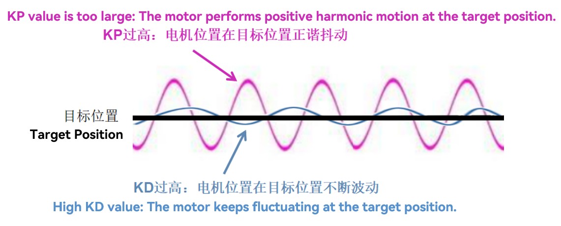
If the position P gain is too high, the actuator may continuously correct small position errors and produce oscillation or positioning jitter around the target.
Therefore, when positioning jitter occurs, reducing the position P gain can be one of the parameters to investigate.
The appropriate value depends on the actual load, mechanical stiffness, reducer characteristics, and desired response.
Position Loop D Gain
The position derivative gain responds to changes in position error and can influence the damping characteristics of the position loop.
An excessively high D gain can introduce oscillation or make the joint response unstable, particularly when measurement noise or mechanical vibration is present.
Position P and D should therefore be considered together rather than adjusted independently without observing the resulting motion.
How to Adjust the Speed Loop of the HPJM Harmonic Joint Actuator?
The speed loop forms the intermediate layer between the current loop and position loop.
Speed Loop P Gain
The speed proportional gain determines the response strength to speed error.
If the gain is too low, the actuator may exhibit a slower speed response.
If the gain is too high, the speed loop can become unstable under certain operating conditions.
Speed Loop I Gain
The speed integral parameter accumulates speed error over time and helps eliminate persistent speed deviation.
However, excessive integral action can affect the settling behavior of the actuator and may increase the time required for the system to stabilize.
The speed loop should therefore be tuned with the actual mechanical load and operating conditions in mind.
Recommended PID Tuning Sequence for the HPJM Harmonic Joint Actuator
A practical tuning process should not modify multiple parameters randomly at the same time.
The basic procedure is:
Stop the actuator → Modify PID parameters → Save parameters → Enable the actuator → Test motion → Repeat if necessary
Before changing parameters, the actuator should be placed in the stopped or disabled state.
For HPJM, users can access the PID parameters through the supported communication interfaces or the Magic software.
A typical tuning sequence is:
1. Confirm the mechanical installation and load
Make sure the harmonic joint actuator is properly installed and operating under the intended load condition.
2. Confirm the current-loop parameters
The current loop has been calibrated before delivery and should generally remain unchanged.
3. Adjust the speed loop
Tune the speed-loop P and I parameters according to the actuator's response under the actual load.
4. Adjust the position loop
Tune position P and D to obtain the desired positioning response without excessive oscillation.
5. Test the actuator
Run repeated positioning movements and observe overshoot, settling behavior, vibration, and positioning jitter.
6. Save the parameters
After achieving stable operation, save the parameters to retain the new settings.
This sequential approach makes it easier to identify which parameter is responsible for a change in behavior.
PID Parameter Adjustment Through CAN, CANopen, and EtherCAT
The HPJM harmonic joint actuator provides PID parameter access through different communication interfaces.
CAN Interface
Through the CAN interface, users can read and write relevant speed-loop and position-loop PID parameters.
The interface can be used to:
Read speed-loop parameters
Read position-loop parameters
Write speed-loop parameters
Write position-loop parameters
Save the modified parameters
This allows the host controller or commissioning software to adjust the actuator according to the application requirements.
CANopen Interface
For CANopen-based systems, PID parameters can be accessed through the corresponding object dictionary indexes.
The HPJM interface includes objects for speed-loop and position-loop parameters, allowing the host controller to read or modify the relevant values.
EtherCAT Interface
For EtherCAT applications, the corresponding objects can likewise be used to access the PID parameters.
This makes the HPJM suitable for robot control systems where the actuator needs to be integrated into a centralized EtherCAT-based motion-control architecture.
For detailed index, sub-index, command, and data-format information, engineers should refer to the HPJM communication protocol documentation.
How to Save PID Parameters After Adjustment?
Changing a PID parameter does not necessarily mean that the new value has been permanently stored.
After completing the tuning process, the parameters need to be saved using the corresponding save command.
For HPJM, the parameter-saving operation can be performed through the supported communication interface.
The basic workflow is:
Adjust → Test → Confirm → Save
This is particularly important during commissioning because otherwise a parameter that appears to work during testing may not be retained after the actuator is restarted.
Using Magic Software to Tune the HPJM Harmonic Joint Actuator
For users who prefer graphical commissioning rather than directly sending CAN or CANopen commands, the HPJM can be adjusted through Magic software.
The general procedure is:
Step 1 — Run Magic Software as Administrator
Right-click the Magic software and select Run as administrator.
Step 2 — Search for the Motor
Select Device Search from the top menu to detect the connected HPJM actuator.
Step 3 — Select the Communication Protocol
Select the appropriate communication protocol, such as CAN or CANopen, according to the actual system configuration.
Step 4 — Select the Communication Channel
Select Channel 1 or Channel 2 according to the analyzer hardware interface.
Step 5 — Select the Baud Rate
Set the communication baud rate corresponding to the actual system configuration.
Step 6 — Select the ID Range
Configure the appropriate device ID range for the connected actuator.
Step 7 — Confirm the Actuator Is Stopped
Enable the motor briefly if required for communication confirmation, then disable it and ensure that the actuator is in the stopped state before changing PID parameters.
Step 8 — Modify and Test the PID Parameters
Adjust the required PID parameters and enable the actuator for testing.
Observe the positioning response and repeat the tuning process if necessary.
Step 9 — Save the Parameters
After the desired response has been achieved, save the parameters through the software.
What Should Engineers Check Before Increasing PID Gain?
PID tuning should not be the first solution for every positioning problem.
Before increasing the gain, engineers should confirm that the mechanical system is properly assembled.
Important factors include:
Mechanical installation:
Check mounting rigidity, shaft alignment, fastening, and load connection.
Load condition:
Confirm that the actual load and inertia are within the actuator's intended operating range.
Transmission condition:
Check whether abnormal friction, mechanical interference, or transmission problems are present.
Encoder feedback:
Confirm that the position feedback is stable and free from abnormal noise.
Communication:
Check whether command transmission and feedback communication are operating correctly.
Operating mode:
Make sure the actuator is being tested under the intended control mode.
If the mechanical system itself has excessive vibration or instability, simply increasing PID gain may make the problem worse.
Why Integrated Harmonic Joint Actuator Design Matters for PID Tuning?
The control performance of a robot joint depends on more than the servo motor itself.
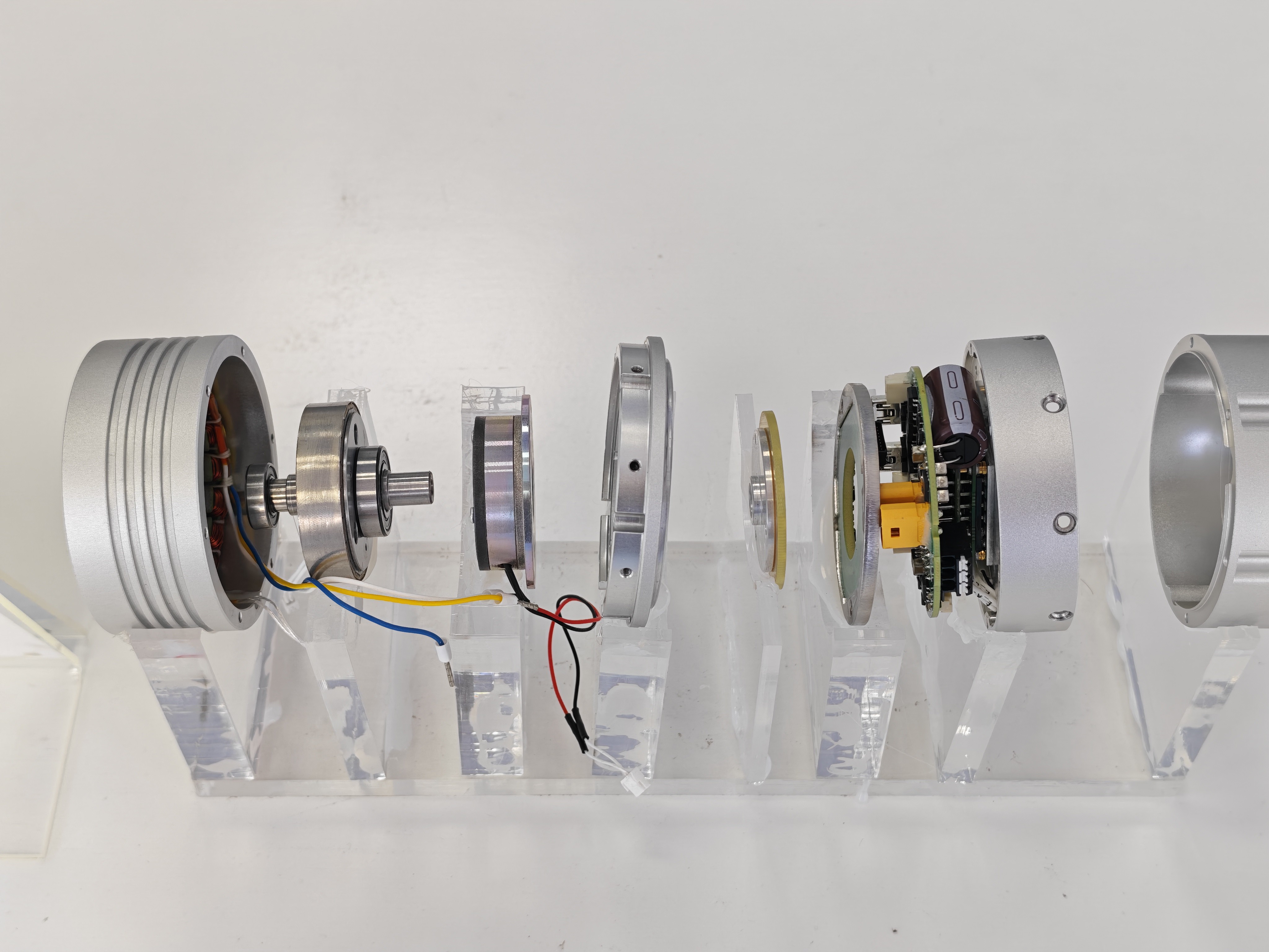
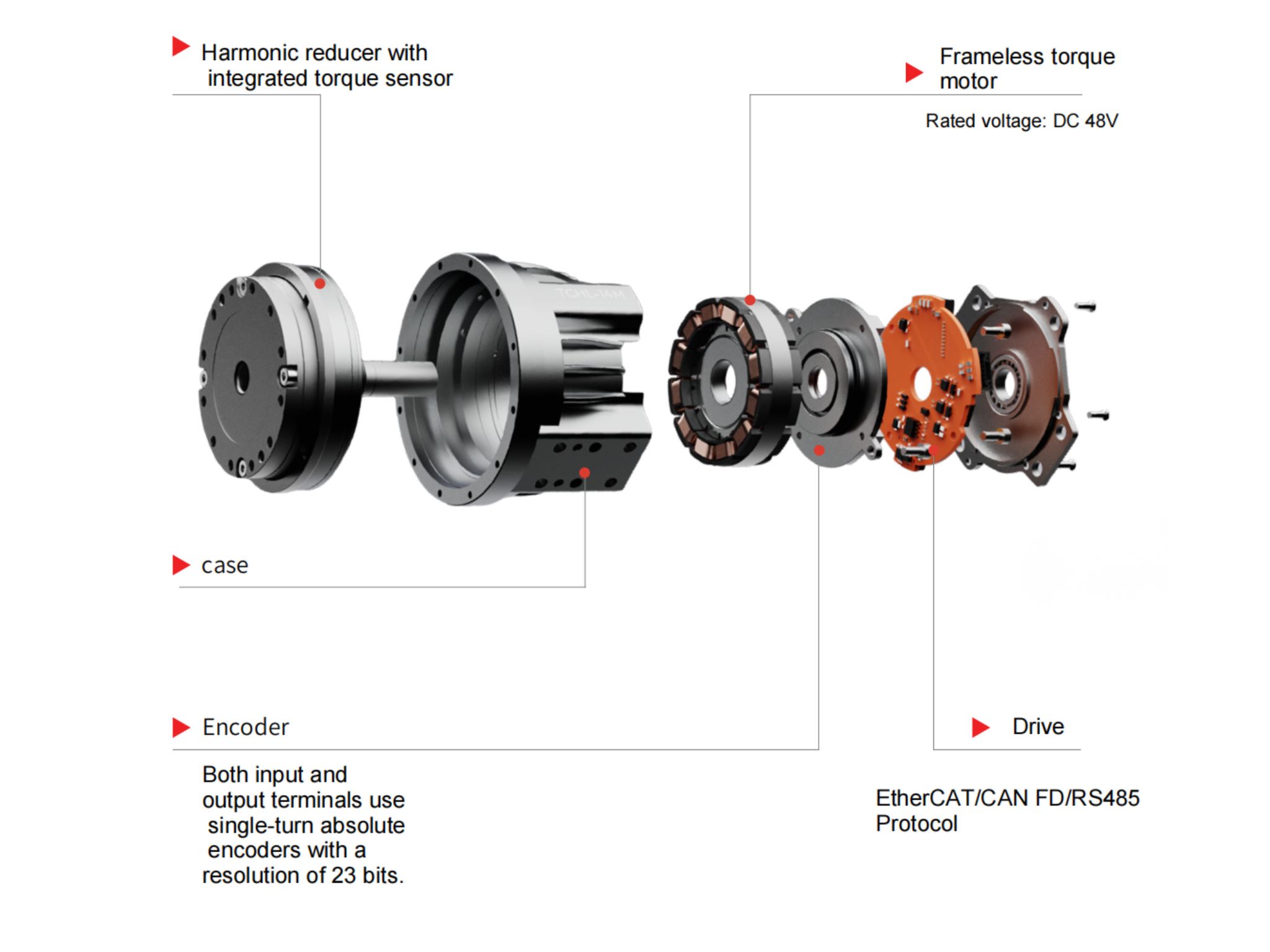
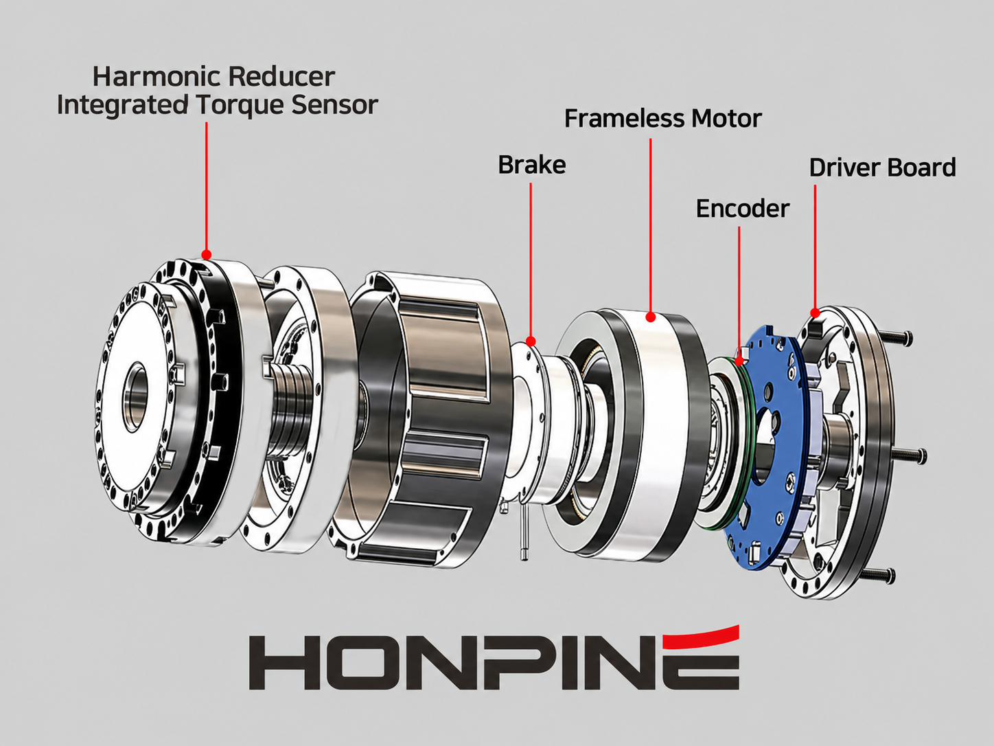
An integrated harmonic joint actuator combines multiple components that directly influence the control response, including the motor, harmonic reducer, encoder, drive electronics, bearings, and mechanical housing.
This integrated architecture allows these components to be matched during development instead of being selected independently and combined at the final system-integration stage.
For robot manufacturers, this can simplify commissioning because the actuator has already been developed around a defined motor-transmission-feedback architecture.
The remaining PID adjustment can then focus primarily on matching the actuator to the specific robot structure and load.
This is particularly valuable for applications such as humanoid robots, robotic arms, collaborative robots, and other multi-axis robotic systems where each joint may experience different inertia and mechanical conditions.
HPJM Harmonic Joint Actuator: From Factory Calibration to Application-Specific Tuning
The HPJM series follows a practical approach to robot joint control.
The motor current loop is calibrated before delivery, providing a predefined foundation for motor control. Users can then adjust the speed and position loops according to their actual application requirements.
This approach allows the same harmonic joint actuator platform to be adapted to different mechanical loads and robotic applications without requiring users to redesign the entire servo-control architecture.
For engineering teams developing robotic joints, the key is not to search for a universal PID parameter.
Instead, the objective is to find a stable parameter combination that matches:
Actuator + Harmonic Transmission + Mechanical Structure + Load + Motion Profile
When these factors are properly matched, the HPJM can achieve stable positioning and responsive motion while minimizing unnecessary oscillation and jitter.
Conclusion
Positioning jitter in a robot joint is often a system-level problem rather than a problem caused by a single component.
For the HPJM harmonic joint actuator, the current loop is calibrated before delivery, while the speed and position loops can be adjusted according to the actual load and application conditions.
A practical tuning process should focus on the relationship between speed-loop P/I and position-loop P/D parameters, while also considering mechanical installation, load inertia, transmission characteristics, encoder feedback, and communication performance.
Whether the HPJM is integrated through CAN, CANopen, EtherCAT, or Magic software, the recommended approach is to make controlled parameter changes, test the actuator under representative conditions, and save the parameters after stable performance is achieved.
For engineers developing humanoid robots, robotic arms, collaborative robots, and other precision robotic systems, proper PID tuning can help the harmonic joint actuator achieve a better balance between positioning accuracy, response speed, and motion stability.
Read More
Learn more about the story of HONPINE and industry trends related to precision transmission.
 What is robot joint actuator?How to Choose the Best Robot Rotary Joint Actuator?In core robot joint transmission solutions, planetary and harmonic rotary actuators each have their own strengths. Choosing the right type based on application requirements is essential to achieve the optimal balance between performance and cost.
 DD Motors VS Harmonic Rotary ActuatorsThis article provides an in-depth comparison between Direct Drive (DD) motors and harmonic rotary actuators, covering their transmission principles, advantages and disadvantages, and typical application fields.
 OMG Ultra Compact Harmonic Drive Joint Module with Built-in Torque SensorHONPINE TCHL series harmonic drive joint module is a game-changing product that achieves disruptive improvements in multiple aspects such as lightweight design, integration level, and connection convenience. This article will analyze its revolutionary enhancements with you.
 The Role of Harmonic Drive Gears in Achieving 5–10 μm Accuracy in Dental Milling MachinesA dental milling machine is a CNC machining system used to directly process digital dental models into restorations such as crowns, bridges, veneers, inlays, and implant abutments. Dental milling machines require far higher operational accuracy and motion stability than ordinary equipment. This article explains how harmonic drive gear help dental milling machines achieve stable, continuous, and controllable operation.
 Why Are Harmonic Rotary Actuators Perfect for Medical Equipment?Harmonic rotary actuators (typically integrated systems consisting of a harmonic drive reducer, frameless torque motor, encoder, and optional brake) are regarded as key components in medical equipment. The core reason is that they simultaneously meet the most stringent medical requirements for precision, compact size, safety, and controllability. The following explanation is structured from three perspectives: technical characteristics, application scenarios, and medical value.
 High-Precision RV Reducers Perfectly Matched for Walking RobotsThe walking axis of a robot is a core component for power transmission and support. RV reducers provide extremely high rigidity, precision, and torque while maintaining a compact size and exceptional reliability, making them an ideal match for the demanding requirements of walking robot joints in terms of load capacity, impact resistance, and precision.
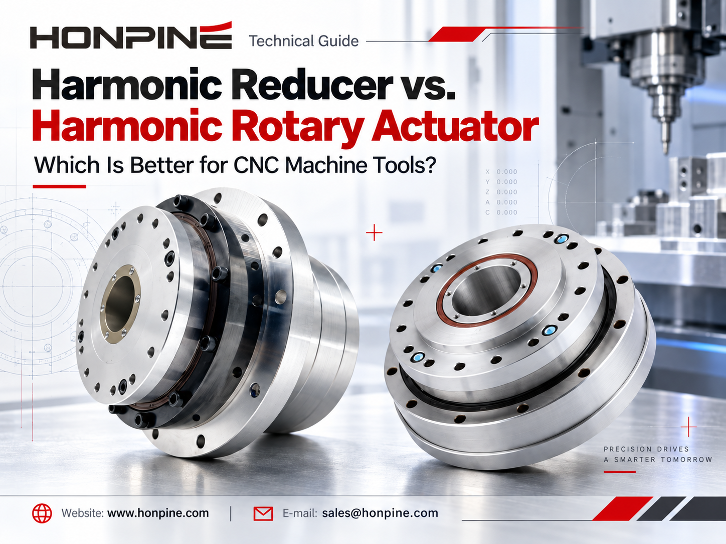
 Harmonic Reducer vs. Harmonic Rotary Actuator: Which Is Better for CNC Machine Tools?Choosing between a harmonic reducer and a harmonic rotary actuator is an important decision in CNC machine tool design. Both solutions offer high-precision motion control, but they differ in integration, installation requirements, rigidity, and system flexibility. For CNC fourth-axis rotary tables and compact five-axis machining systems, selecting the right harmonic drive can significantly influence machine performance. In this article, HONPINE Technical Director Theodore Li compares harmonic reducers and harmonic rotary actuators to help engineers identify the most suitable solution for their CNC applications.
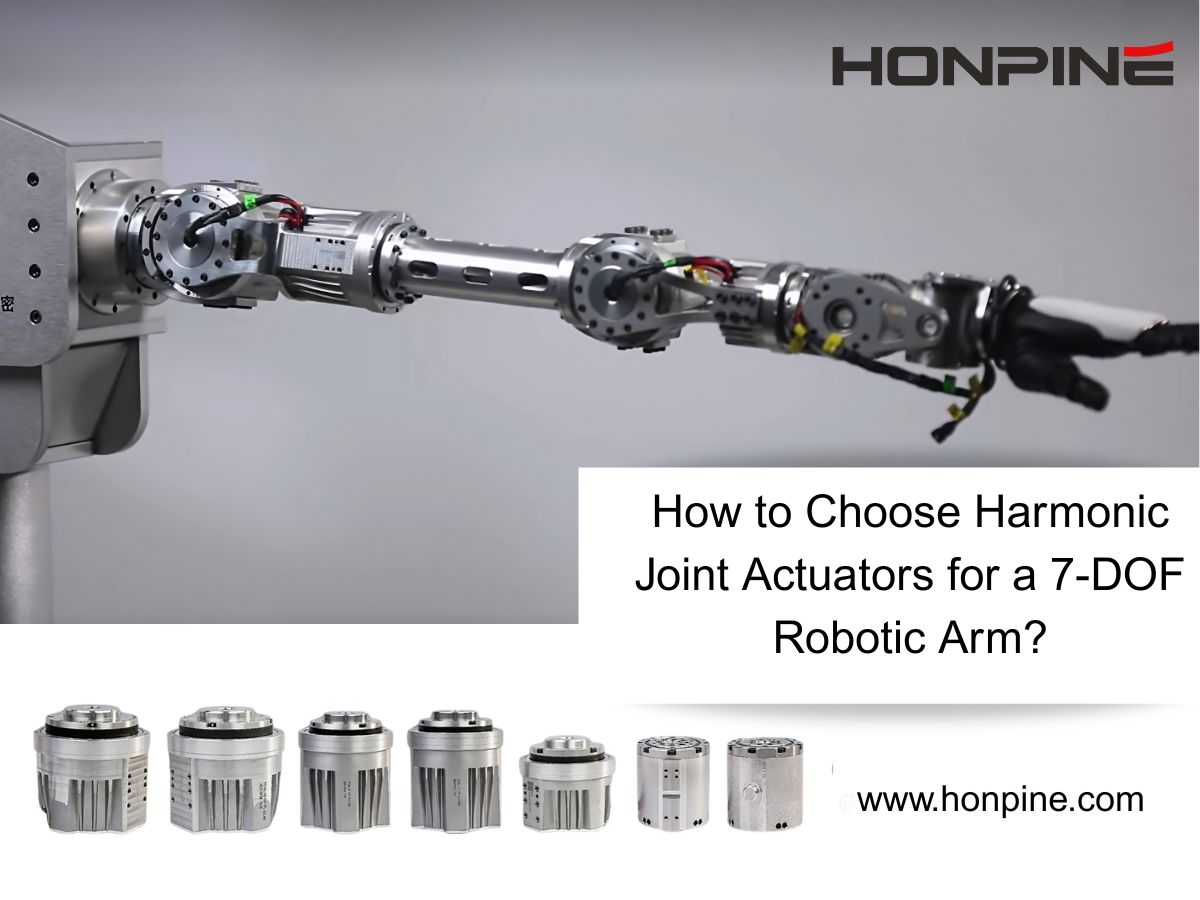
 How to Choose Harmonic Joint Actuators for a 7-DOF Robotic Arm?I'm Theodore Li, Technical Director at HONPINE. Choosing harmonic joint actuators for a 7-DOF robotic arm starts with the torque, weight, and installation needs of each joint. This guide uses a TCHL 20 shoulder and TCHL 14 wrist configuration as an example, then explores torque sensing, compliant control, and HAG Series considerations for demanding robotic applications.
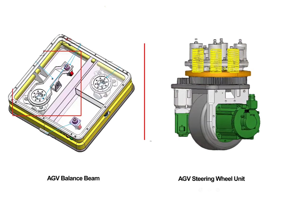
 AGV Suspension: Should You Choose a Balance Beam or a Spring-Loaded Steering Drive Unit?Choosing an AGV suspension system starts with the vehicle’s load range and floor conditions. Balance beams and spring-loaded steering drive units offer different approaches to maintaining wheel contact and managing wheel loads. This HONPINE guide compares both options and explains how to evaluate traction, suspension travel, installation space, and maintenance before choosing a configuration.
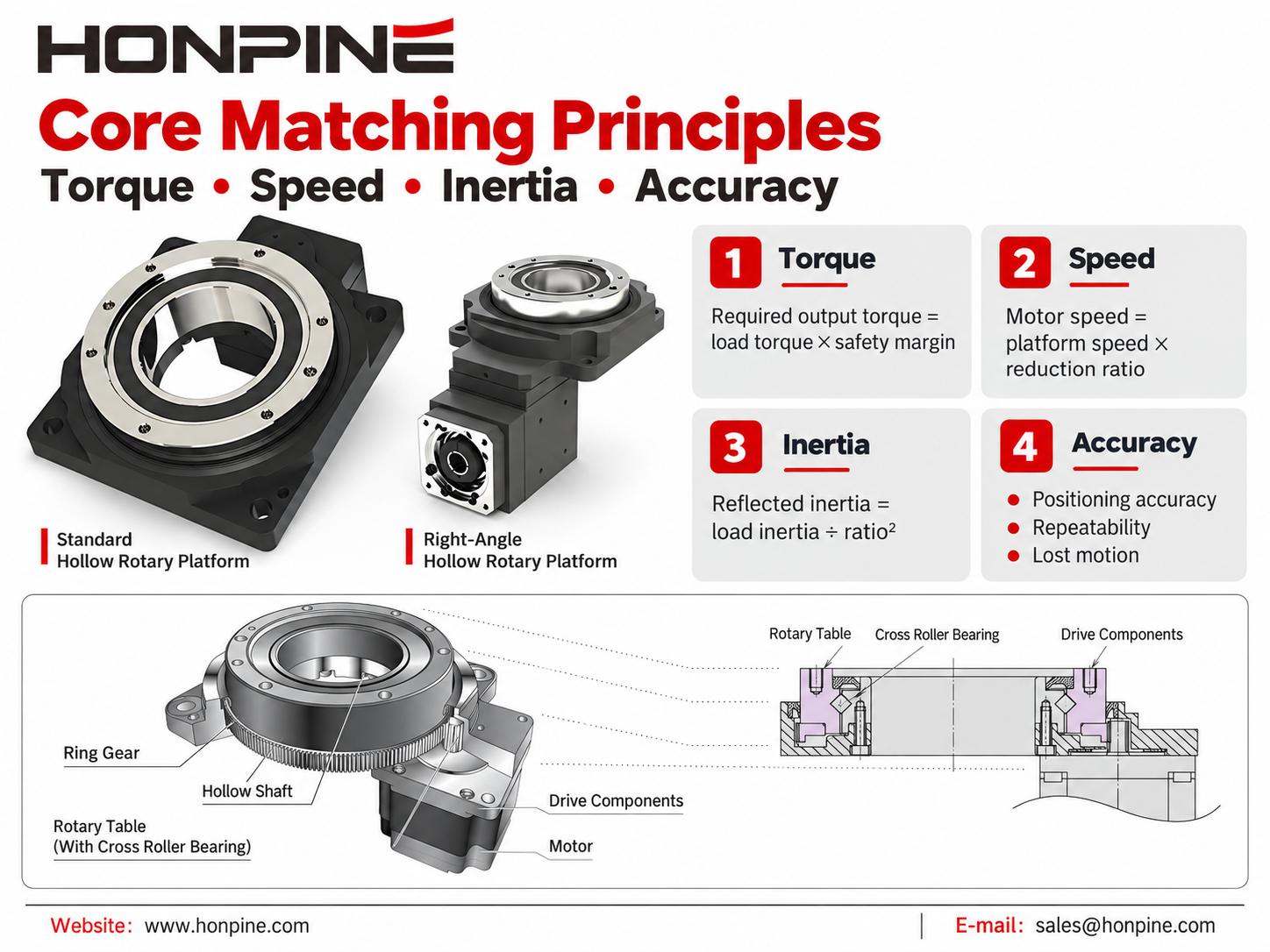
 Hollow Rotary Platform Motor Matching: A Complete GuideSelecting the right motor for a hollow rotary platform is essential for achieving precise positioning, stable operation, and efficient automation. This guide explains how to match servo motors, stepper motors, and brushless DC motors with hollow rotary platforms based on torque, speed, inertia, accuracy, and installation requirements. Explore practical motor selection guidelines, typical application combinations, and space-saving mounting solutions to find the right configuration for your automation project.
 Can Robots Feel Touch? HONPINE HAG Force-Controlled Harmonic Robot Joint MotorsCan robots respond to a gentle touch? The HONPINE HAG robot joint motor with torque sensor combines a harmonic reducer, integrated torque sensing, and closed-loop control to detect external forces and support smooth, compliant motion. In this article, HONPINE founder Allen Li demonstrates the module's response to light contact and hand-guided movement, explains its key force-control technologies, and shares the vision behind joint modules designed for practical industrial robotics.
 Does a Higher Gearbox Ratio Mean More Torque? Planetary, Harmonic, and RV Gearboxes ExplainedDoes a higher gearbox ratio mean more torque? This engineering guide explains the relationship between gearbox ratio, output torque, and output speed, and compares planetary gearboxes, harmonic gearboxes, and RV gearboxes. Learn why reduction ratio alone cannot determine gearbox torque capacity, efficiency, dynamic response, precision, or service life, and what engineers should consider when selecting a gearbox for robotics, CNC machines, servo systems, and industrial motion control.
Double Click
We provide harmonic drive reducer,planetary reducer,robot joint motor,robot rotary actuators,RV gear reducer,robot end effector,dexterous robot hand
 What is robot joint actuator?How to Choose the Best Robot Rotary Joint Actuator?In core robot joint transmission solutions, planetary and harmonic rotary actuators each have their own strengths. Choosing the right type based on application requirements is essential to achieve the optimal balance between performance and cost.
 DD Motors VS Harmonic Rotary ActuatorsThis article provides an in-depth comparison between Direct Drive (DD) motors and harmonic rotary actuators, covering their transmission principles, advantages and disadvantages, and typical application fields.
 OMG Ultra Compact Harmonic Drive Joint Module with Built-in Torque SensorHONPINE TCHL series harmonic drive joint module is a game-changing product that achieves disruptive improvements in multiple aspects such as lightweight design, integration level, and connection convenience. This article will analyze its revolutionary enhancements with you.
 Harmonic Reducer vs. Harmonic Rotary Actuator: Which Is Better for CNC Machine Tools?Choosing between a harmonic reducer and a harmonic rotary actuator is an important decision in CNC machine tool design. Both solutions offer high-precision motion control, but they differ in integration, installation requirements, rigidity, and system flexibility. For CNC fourth-axis rotary tables and compact five-axis machining systems, selecting the right harmonic drive can significantly influence machine performance. In this article, HONPINE Technical Director Theodore Li compares harmonic reducers and harmonic rotary actuators to help engineers identify the most suitable solution for their CNC applications.
 How to Choose Harmonic Joint Actuators for a 7-DOF Robotic Arm?I'm Theodore Li, Technical Director at HONPINE. Choosing harmonic joint actuators for a 7-DOF robotic arm starts with the torque, weight, and installation needs of each joint. This guide uses a TCHL 20 shoulder and TCHL 14 wrist configuration as an example, then explores torque sensing, compliant control, and HAG Series considerations for demanding robotic applications.
 AGV Suspension: Should You Choose a Balance Beam or a Spring-Loaded Steering Drive Unit?Choosing an AGV suspension system starts with the vehicle’s load range and floor conditions. Balance beams and spring-loaded steering drive units offer different approaches to maintaining wheel contact and managing wheel loads. This HONPINE guide compares both options and explains how to evaluate traction, suspension travel, installation space, and maintenance before choosing a configuration.
 Hollow Rotary Platform Motor Matching: A Complete GuideSelecting the right motor for a hollow rotary platform is essential for achieving precise positioning, stable operation, and efficient automation. This guide explains how to match servo motors, stepper motors, and brushless DC motors with hollow rotary platforms based on torque, speed, inertia, accuracy, and installation requirements. Explore practical motor selection guidelines, typical application combinations, and space-saving mounting solutions to find the right configuration for your automation project.
 Can Robots Feel Touch? HONPINE HAG Force-Controlled Harmonic Robot Joint MotorsCan robots respond to a gentle touch? The HONPINE HAG robot joint motor with torque sensor combines a harmonic reducer, integrated torque sensing, and closed-loop control to detect external forces and support smooth, compliant motion. In this article, HONPINE founder Allen Li demonstrates the module's response to light contact and hand-guided movement, explains its key force-control technologies, and shares the vision behind joint modules designed for practical industrial robotics.
 Does a Higher Gearbox Ratio Mean More Torque? Planetary, Harmonic, and RV Gearboxes ExplainedDoes a higher gearbox ratio mean more torque? This engineering guide explains the relationship between gearbox ratio, output torque, and output speed, and compares planetary gearboxes, harmonic gearboxes, and RV gearboxes. Learn why reduction ratio alone cannot determine gearbox torque capacity, efficiency, dynamic response, precision, or service life, and what engineers should consider when selecting a gearbox for robotics, CNC machines, servo systems, and industrial motion control.
 High-Precision Hollow Harmonic Rotary Actuator for CNC Machines and Heavy-Duty Rotary AxesHONPINE 58 Series Hollow Harmonic Rotary Actuator is designed for CNC rotary tables, precision rotary axes, laser processing equipment, and heavy-duty rotary positioning applications. With a 50 mm hollow bore, up to 2,722 N·m peak torque, integrated crossed roller bearing, multi-turn absolute encoder options, positioning accuracy below 30 arcsec, and repeat positioning accuracy below 5 arcsec, it combines high torque capacity with precision rotary motion and flexible mechanical integration.
 How Does the HONPINE JRM Planetary Robot Joint Module Address Temperature Rise in Continuous Operation?HONPINE JRM planetary robot joint modules are designed for long-duration and high-load robotic operation. This article examines how motor electromagnetic optimization, high-efficiency planetary transmission, GaN-based drive technology, and system-level low-loss design help control temperature rise. Using the C6345 planetary robot joint module as a test example, HONPINE also presents full-load thermal validation under continuous operation, including motor efficiency up to 92%, planetary gearbox efficiency up to 97%, and a final equilibrium temperature of 61.42°C at a 25°C ambient temperature.
 Direct Drive Motor Sizing: A Complete Guide to Torque Calculation and SelectionSelecting a direct drive motor for a precision rotary system requires more than matching motor torque to the equipment weight. Engineers need to evaluate gravity torque, inertial torque, wind torque, friction, rotational inertia, speed, acceleration, duty cycle, and positioning requirements. In this guide, Theodore Li, Technical Director at HONPINE, explains a practical approach to direct drive motor sizing and torque calculation using an azimuth and elevation turntable as an engineering example. The article covers continuous and peak torque calculation, motor selection criteria, and the application of frameless direct drive motors in integrated rotary systems.