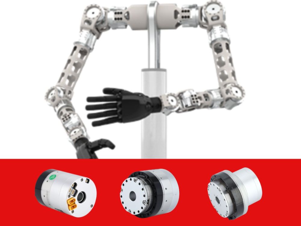
How to Select the Most Suitable RV Reducer Based on Requirements
As a core component of precision transmission, RV reducers are widely used in industrial robots, machine tool rotary tables, automated equipment, and other fields. They are highly regarded for their high precision, high rigidity, and high load capacity. However, for many companies using RV reducers for the first time, selecting the right model from numerous options and parameters often poses a significant challenge. This article will start with the basic principles of RV reducers, delve into their current status and key parameters, and explain the selection steps in detail, enabling you to easily master the essentials of RV reducer selection. Both beginners and experienced engineers can benefit from this guide.
1. Working Principle of RV Reducers: Why Are They So Outstanding?
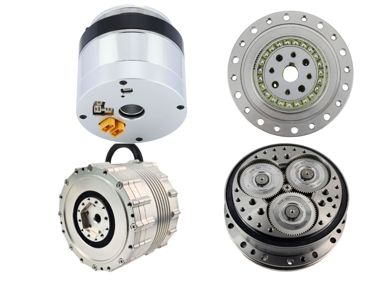
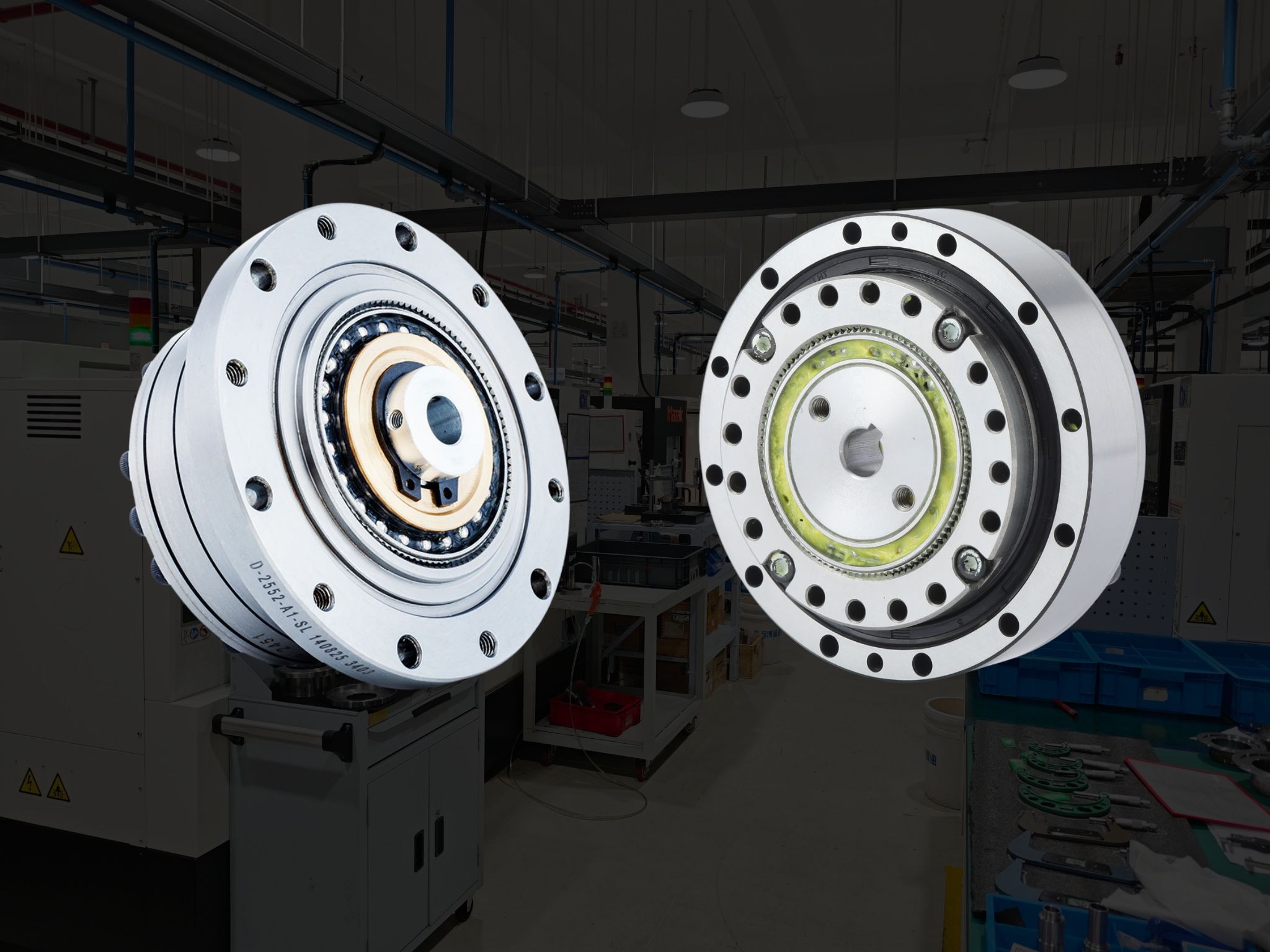
The RV reducer (Rotary Vector Reducer) is a high-precision control reducer that uses a planocentric reduction mechanism. Its core lies in a two-stage reduction design:
First Stage Reduction: Planetary Gear Reduction. The rotation of the input shaft is transmitted to the planetary gears via the input gear, achieving initial speed reduction.
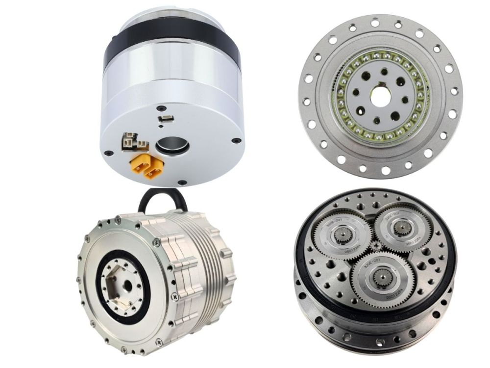
Second Stage Reduction: Differential Gear Reduction (Cycloidal Pin Wheel Mechanism). The planetary gears are connected to the crankshafts, which drive the RV (cycloid) gears in an eccentric motion. The RV gear has one less tooth than the pin wheel, enabling high reduction ratios.
This design allows many gear teeth to be engaged simultaneously in the RV reducer, resulting in a compact, lightweight size while offering high rigidity and resistance to overload. Furthermore, due to small backlash, low rotational vibration, and low inertia, RV reducers enable smooth operation and high-precision positioning.
The reduction ratio formula is:
R = 1 + (Z2 / Z1) * Z4
Where Z1 is the input gear teeth, Z2 is the planetary gear teeth, and Z4 is the pin wheel teeth number. The total reduction ratio i = 1/R.
2. How to Choose the Suitable Series Based on the Application Field of RV Reducers
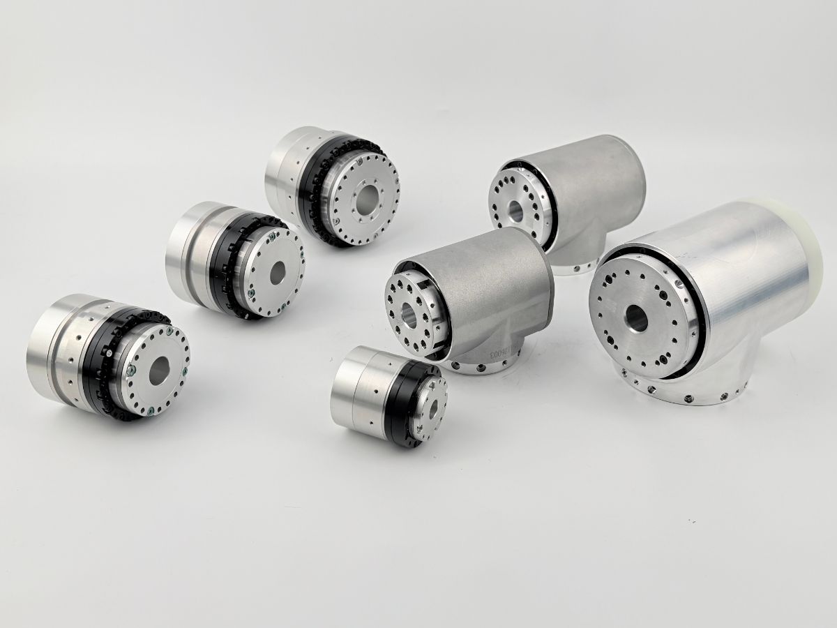
You can select the most appropriate series based on the characteristics of the three main RV reducer series (using HONPINE as an example):
E Series: Economic type, suitable for general industrial applications.
C Series: Hollow structure, convenient for cable routing, suitable for robot joints.
N Series: Compact and lightweight, optimized performance, used for high-precision applications.
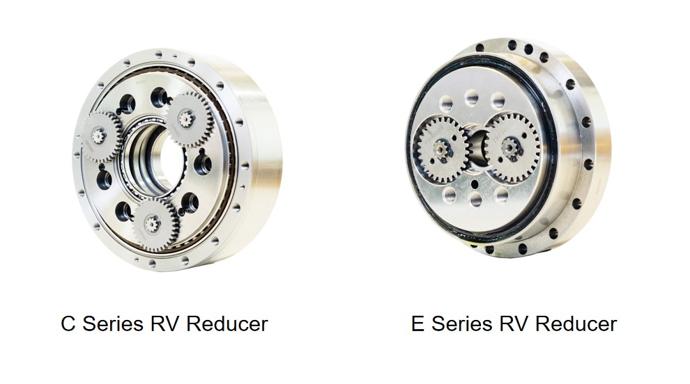
These products are widely used in:
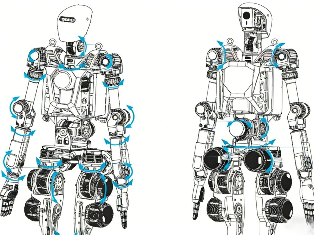
Industrial Robots: Such as joint parts of 6-axis robots.
Machine Tools: Tool turrets, ATC tool changers, etc.
Semiconductor Equipment: Precision positioning stages.
AGVs: Drive units.
3. Common Knowledge of RV Reducers: Key Parameter Analysis
Rated Torque (T₀): The allowable torque when the reducer operates at the rated output speed. It is not the maximum load limit.
Permissible Start/Stop Torque (Ts₁): The maximum allowable torque during acceleration/deceleration, typically 2.5 times the rated torque.
Permissible Instantaneous Maximum Torque (Ts₂): The allowable value during emergency stops or impact, typically 5 times the rated torque.
Permissible Output Speed (Ns₀): The maximum output speed under no load, affected by temperature and load conditions.
Backlash and Lost Motion: Backlash refers to the torsional angle when torque is zero. Lost motion is the width of the hysteresis curve within ±3% of the rated torque. RV reducers are typically controlled within 1 arcmin.
Torsional Stiffness: The torque required per unit torsional angle, reflecting the reducer's resistance to deformation.
Life: The rated life is typically 6000 hours (under rated torque and speed).
4. How to Select an RV Reducer to Ensure System Stability
Step 1: Define Load Conditions
First, clarify the equipment's mounting orientation, mass, shape, and operating conditions.
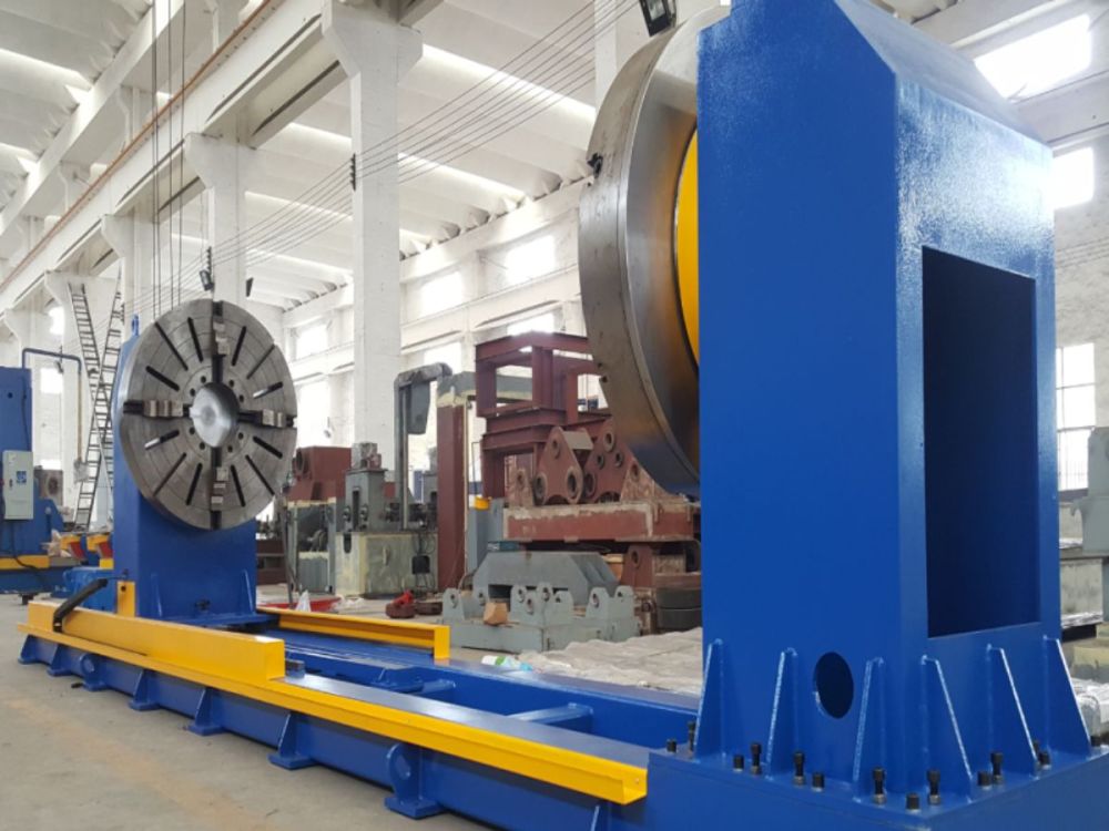
Example: Horizontal rotary table, disc mass 180kg, 4 workpieces each 20kg, rotation angle 180°, cycle time 20s, daily operation 12 hours.
Step 2: Confirm Usage Environment
Ambient temperature should be between -10°C and 40°C, reducer surface temperature should not exceed 60°C. Humidity below 85%, no condensation.
Step 3: Calculate Load Moment of Inertia and Constant Running Torque
Moment of Inertia Calculation: J_L = (1/8) * M * D² (Where M is mass (kg), D is diameter (m). Note: Ensure unit consistency, D in meters).
Constant Running Torque Calculation: T_s = (μ * M * g * D_bearing) / 2 (Where μ is the friction coefficient, typically 0.015; g is gravity acceleration 9.8 m/s²; D_bearing is the pitch diameter of the support bearing (m)).
Step 4: Set Operating Mode
Determine acceleration/deceleration time and constant speed. Assuming output speed 15 rpm, rotation time 2.5s, then acceleration time 0.5s, deceleration time 0.5s, constant speed time 1.5s.
Step 5: Calculate Acceleration/Deceleration Torque
Acceleration Torque: T_acc = J_L * α (α is angular acceleration = (2πN) / (60 * t_acc))
Total Acceleration Torque: T₁ = T_acc + T_s
Total Deceleration Torque: T₃ = T_dec - T_s (T_dec = J_L * α_dec; motor provides braking force)
Maximum Torque: T_max = max(|T₁|, |T₃|)
Step 6: Calculate Average Speed and Average Load Torque
Average Speed (N_m): N_m = (t₁*N₁ + t₂*N₂ + t₃*N₃) / (t₁ + t₂ + t₃)
Average Load Torque (T_m): T_m = ³√[ (t₁*N₁*T₁^(10/3) + t₂*N₂*T₂^(10/3) + t₃*N₃*T₃^(10/3)) / (t₁*N₁ + t₂*N₂ + t₃*N₃) ]
Step 7: Calculate Required Rated Torque Based on Life Requirement
Daily Cycles: (Daily Operation Hours * 3600) / Cycle Time (s)
Daily Operation Time (for motion): Daily Cycles * Rotation Time per Cycle (s)
Annual Operation Time (H): Daily Operation Time (hours) * Operating Days per Year
Required Rated Torque (T_R): T_R = T_m * ³√[ (Annual Operation Time * Design Life Years) / K ] (Where K is the rated life, typically 6000 hours).
Step 8: Verify Key Parameters
Start/Stop Torque: Ensure T₁ and T₃ are less than Ts₁.
Output Speed: Average speed N_m should be less than the permissible output speed Ns₀.
Emergency Stop Impact: Impact torque T_emergency should be less than Ts₂, and the number of impacts should be within the allowable range.
Thrust Load and Moment Load: Confirm they are within the safe range according to the permissible moment load diagram.
Step 9: Calculate Service Life and Confirm
Life Time: L_h = K * (T_rated / T_m)³ * (N_rated / N_m) (Check manufacturer's formula, this is a common form)
Service Life (Years): L_h / (Annual Operation Hours)
Should be greater than the required service life.
Step 10: Final Model Selection
Based on the above calculations, select a model that meets all conditions, such as RV-20E.
5. Key Points to Note When Designing the Structure for RV Reducer Selection
Mounting Precision: Ensure flatness and perpendicularity of mounting surfaces to avoid eccentric loads. Recommend using a dial indicator for detection, with runout controlled within 0.02mm.
Lubricant Selection: Common greases like VIGOGREASE REO. Standard replacement cycle is 20000 hours; it needs shortening in high-temperature environments.
Temperature Management: Surface temperature must not exceed 60°C, otherwise cooling or derating is required.
Small Angle Operation: For rotation angles less than 10°, lubrication is insufficient; consult the manufacturer.
Bolt Fastening: Use disc spring washers and socket head cap screws, tightened to standard torque to prevent loosening.
6. RV Reducer Selection Step Suggestions
Determine Work Load & Operating Conditions: Max. working torque, inertia, operating frequency, motion mode (continuous/intermittent/impact).
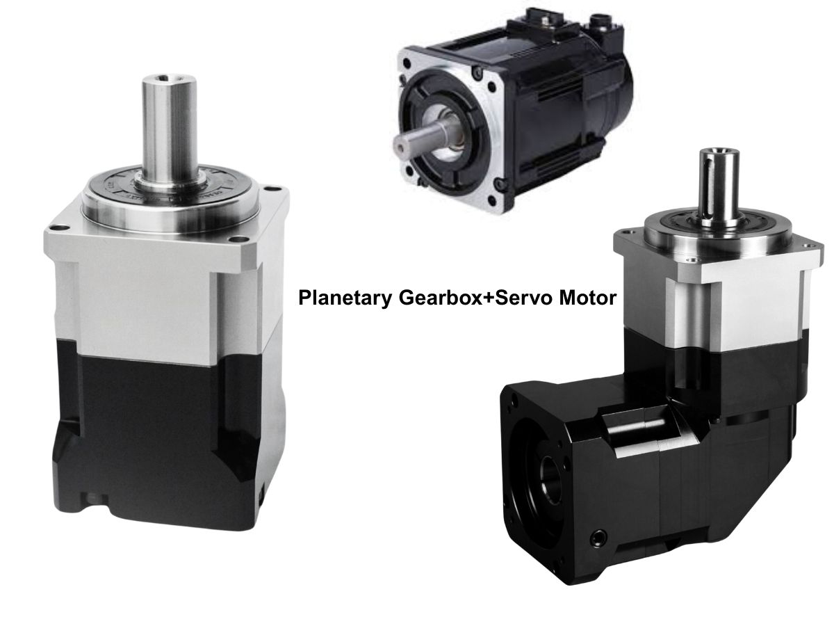
Calculate Theoretical Reduction Ratio & Output Torque: Combine servo motor parameters and power characteristics.
Include Safety Factor (20%-30%): Consider start-up impact, emergency stops, inertial load variations.
Select RV Reducer Model: Based on output torque, reduction ratio, size matching the motor.
Confirm Mounting & Interface Compatibility: Check flange dimensions, output shaft type, seal space.
Final Verification of Accuracy, Rigidity & Life Requirements: Combined with application scenario (robot, machine tool, semiconductor equipment, etc.).
Selecting an RV reducer is a systematic project that requires comprehensive consideration of factors such as load, operating mode, and life requirements. By following the steps in this article, you can avoid common pitfalls and select the most suitable model. Remember, precise selection is the cornerstone of stable equipment operation.
Read More
Learn more about the story of HONPINE and industry trends related to precision transmission.
Double Click
We provide harmonic drive reducer,planetary reducer,robot joint motor,robot rotary actuators,RV gear reducer,robot end effector,dexterous robot hand

