Compact Bore Input Right Angle 90-degree Spiral Bevel Gearbox

●  Introduction

A bore-input right angle spiral bevel gearbox features an input shaft with a bore design and a connecting flange plate for direct motor coupling. Its input and output shafts are arranged at a 90-degree angle, achieving power redirection through gear mechanisms such as spiral bevel gears or bevel gears. The core design focuses on optimizing spatial efficiency, making it suitable for industrial automation equipment, CNC machine tools, packaging machinery, and other applications requiring compact installation or directional power transmission. Depending on specific operational demands, housing materials vary: aluminum housings are prioritized for automated systems and weight-sensitive scenarios; stainless steel housings cater to corrosion-resistant environments like food processing, pharmaceuticals, and marine engineering; alloy steel housings are engineered for heavy-duty applications such as smart warehouse lifting systems. Clients must communicate their operational context and material requirements to manufacturers during selection to ensure optimal gearbox performance.
Contact Us

Features

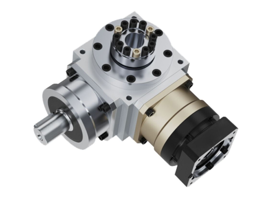
● User-Friendly Design

Features a shaft bore input and a connecting flange for direct motor connection, ensuring ease of use.


● The internal bevel gear structure and perpendicular input/output shaft arrangement minimize equipment footprint, making it particularly suitable for confined installation spaces.


● High Transmission Efficiency and Low Energy Consumption

Employs precision gear meshing and an optimized lubrication system, achieving a transmission efficiency of over 95% while reducing energy loss.


● High Precision and Low Noise

The combination of helical or bevel gears with precision machining results in minimal backlash, accurate positioning, smooth operation, and low noise levels.


● High Load Capacity and Durability

High-strength materials (such as premium forged steel) and heat treatment processes enhance load-bearing capacity, supporting significant radial and axial loads and extending service life.


● Diverse Output Configurations

Available in various output configurations: hollow input with shaft output, hollow input with hollow output, shaft input with shaft output, and shaft input with hollow output.


● Suitable Applications

Ideal for lifting platforms and single-motor driven multi-module systems.

Specification

Sheet 1

Reducer performance data (the performance and specifications of the ATB series are the same as those of the AT series)
SpecificationsStageReduction RatioANT065 FL
NT065 FL1
NT065 FH
NT065 FC
NT065 FR1
NT075 FL
NT075 FL1
NT075 FH
NT075 FC
NT075 FR1
NT090 FL
NT090 FL1
NT090 FH
NT090 FC
NT090 FR1
NT110 FL
NT110 FL1
NT110 FH
NT110 FC
NT110 FR1
NT140 FL
NT140 FL1
NT140 FH
NT140 FC
NT140 FR1
NT170 FL
NT170 FL1
NT170 FH
NT170 FC
NT170 FR1
NT210 FL
NT210 FL1
NT210 FH
NT210 FC
NT210 FR
NT240 FL
NT240 FL1
NT240 FH
NT240 FC
NT240 FR1
NT280 FL
NT280 FL1
NT280 FH
NT280 FC
NT280 FR1
Rated Output Torque T₂N (Nm)Nm112545781503605851,3002,1503,200
1.52545781503605851,3002,1503,200
22442681503305441,2202,0103,050
31833541202704501,0201,6502,850
41328481002243768601,4102,300
5122540851963207401,2102,000
27121233919191195358358
10242868150208208430846846
151833541202703126451,2691,269
201328481002243768601,4101,692
25122540851963207401,2102,000
35122540851963207401,2101,790
50122540851963207401,2101,465
375---1202103125851,2691,269
100---1002243767801,4101,692
125---851963207401,2102,000
150---120135312390975975
200---1001803765201,3001,300
250---851963206501,2101,625
350---851963207401,2101,790
500---851963207401,2101,465
Maximum Accelerating Torque T₂BNm1,2,31~5001.5 times rated output torque
Maximum Accelerating Input Speed n₁Brpm11~57,5006,5005,5004,5003,5003,0002,2002,0001,700
27~508,0008,0006,0006,0006,0006,0004,8003,6003,600
375~500---8,0008,0006,0006,0006,0006,000
Backlash Barcmin11~5≤6≤6≤6≤6≤6≤6≤6≤6≤6
27~50≤8≤8≤8≤8≤8≤8≤8≤8≤8
375~500


≤10≤10≤10≤10≤10≤10
Permissible Radial Load F₂rBc  Output shaft d2N1,2,31~5009001,1001,7002,7004,8006,60011,50016,00018,000
Permissible Axial Load F₂aBc Output shaft d2N1,2,31~5004505508501,3502,4003,3005,7508,5009,000
Service Life Dhr1,2,31~50020,000
Efficiency η%11~5≥98%
237~500≥94%
Operating Temperature1,2,31~500-10℃~90℃
Lubrication


Synthetic lubricating grease
Noise Level(n₁=1500rpmdB(A)1,2,31~500≤71≤72≤76≤77≤78≤79≤81≤83≤84

Sheet 2

Speed Reducer Performance Data
SpecificationStageReduction RatioANT065 FL
NT065 FL1
NT065 FH
NT065 FC
NT065 FR
NT075 FL
NT075 FL1
NT075 FH
NT075 FC
NT075 FR1
NT090 FL
NT090 FL1
NT090 FH
NT090 FC
NT090 FR1
NT110 FL
NT110 FL
NT110 FH
NT110 FC
NT110 FR1
NT140 FL
NT140 FL
NT140 FH
NT140 FC
NT140 FR1
NT170 FL
NT170 FL1
NT170 FH
NT170 FC
NT170 FR
NT210 FL
NT210 FL1
NT210 FH
NT210 FC
NT210 FR1
NT240 FL
NT240 FL1
NT240 FH
NT240 FC
NT240 FR
NT280 FL
NT280 FL1
NT280 FH
NT280 FC
NT280 FR
Moment of Inertia J₁110.511.303.147.6223.5459.09195.96365.38787.63
1.50.461.152.806.6519.3449.38156.02279.62584.28
20.441.102.686.2317.7245.44140.80245.78500.26
30.431.092.646.0817.1644.11135.51233.75471.56
40.431.082.636.0517.0343.79134.14230.77464.76
50.431.082.636.0416.9943.69133.71229.71462.08
270.150.150.502.792.792.799.9129.2629.26
100.150.150.502.802.802.809.9629.4329.43
150.150.150.502.802.802.809.9629.4329.43
200.150.150.502.802.802.809.9629.4329.43
250.150.150.502.802.802.809.9629.4329.43
350.150.150.502.792.792.799.9129.2629.26
500.150.150.502.792.792.799.8929.2029.20
375---0.150.150.500.502.802.80
100---0.150.150.500.502.802.80
125---0.150.150.500.502.802.80
150---0.150.150.500.502.792.79
200---0.150.150.500.502.792.79
250--
0.150.150.500.502.792.79
350
-
0.150.150.500.502.792.79
500---0.150.150.500.502.792.79